VeriFast
TM
MicroView 1.0 – User Manual – Version 1.9
29
Run Screen
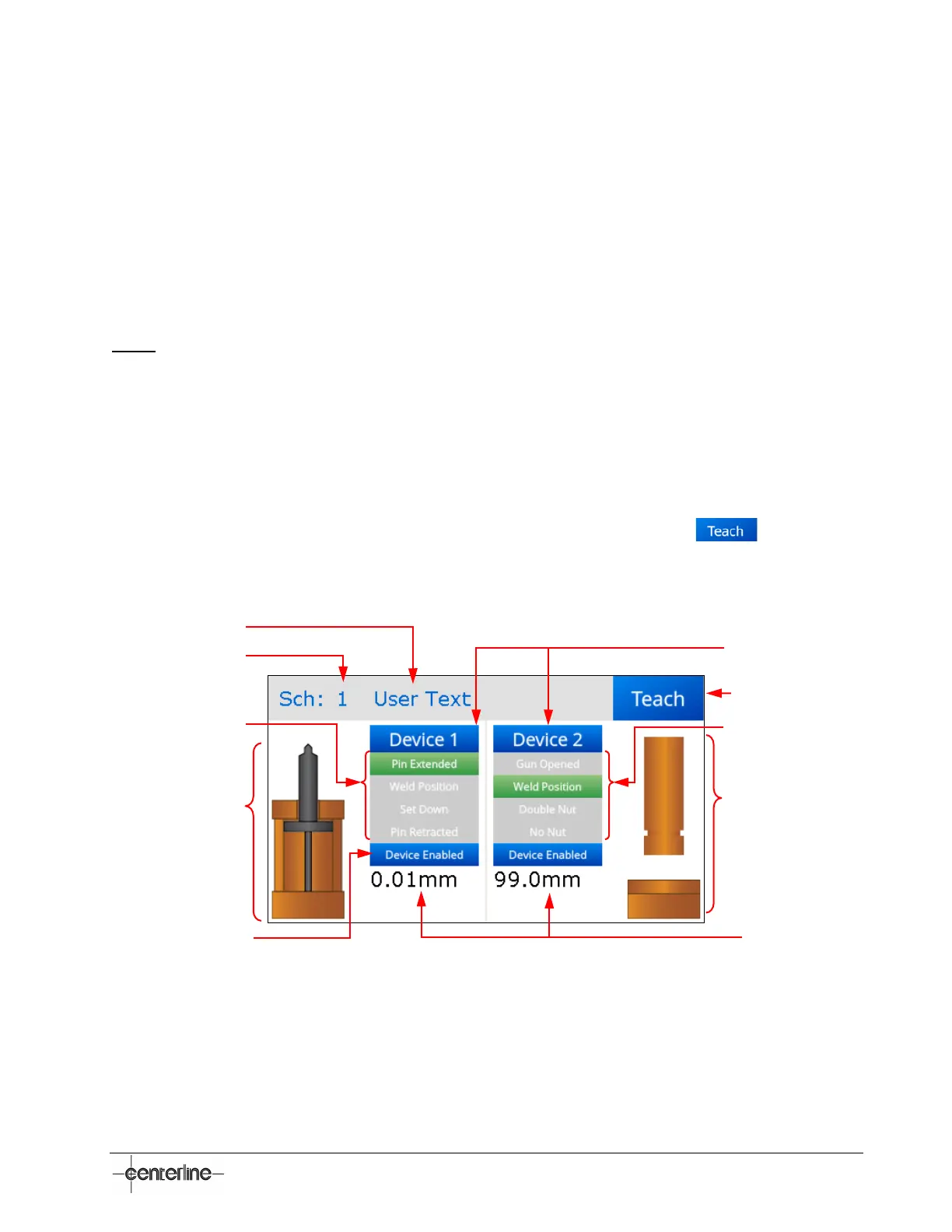
The Run screen (see Figure 11 below) is the normal operating screen of the MicroView. It is used
for monitoring the processes associated with the devices connected to the MicroView. While on
this screen, the MicroView is actively scanning the analog inputs at a rate of 800 Hz.
The user can watch the live data for both devices (Device 1 and Device 2) connected to the
MicroView. The parameters that are monitored on this screen are listed separately for each device
and are in concordance with the type of the device (e.g., Pin Extended, Weld Position, Set Down,
and Pin Retracted for VeriFast™ LVDT; Gun Opened, Weld Position, Double Nut, and No Nut for
LPT; and so on). The parameters are generally listed as P1, P2, P3, P4 for a generic device.
Note: For VeriFast™ MicroView 5-port Single Device configurations, a VeriFast™ LVDT only will
be connected and operational as Device 1. An image and parameters for Device 2 can still be
displayed on the screen, but they are not functional.
As an example, Figure 11 below shows a VeriFast™ LVDT connected to the MicroView as
Device 1, and an LPT connected as Device 2. The instant setting on each list is highlighted (see
the green highlighted areas for “Pin Extended” for VeriFast™ LVDT and “Weld Position” for the
LPT).
A real time animation of the state of both devices is also displayed on this screen.
To further navigate to the Teach Screen (see next sub-section), press on the
button. You
will be prompted for the user access password.
Figure 11 – Run Screen
Connected devices
Monitored parameters
for VeriFast™ LVDT
Real time animation for LPT
Access to Teach screen
(password required)
Live data
Real time animation
for VeriFast™ LVDT
Monitored parameters for LPT
Schedule Number
Schedule Name
Device Status
(Device Enabled (blue) or
Device Bypassed (red))
 Loading...