26
VeriFast
TM
MicroView 1.0 – User Manual – Version 1.9
Re-Calibrating the Signal Conditioner (If necessary)
Re-Calibrating the Signal Conditioner for Most Applications
When delivered to the customer, the VeriFast™ LVDT used in connection with the MicroView is
fully calibrated for use with a 22 mm weld pin stroke. If a 50 mm weld pin stroke is being used, or
if, for any other reason, you suspect that your equipment needs to be recalibrated, follow the
instructions below.
Calibrating the VeriFast™ LVDT Signal Conditioner consists of entering the Calibration Mode (on
the Signal Conditioner) and moving the weld pin to set the extended and retracted positions, which
will correspond to the minimum and maximum output voltage.
The Signal Conditioner returns to Operating Mode immediately after both positions have been set.
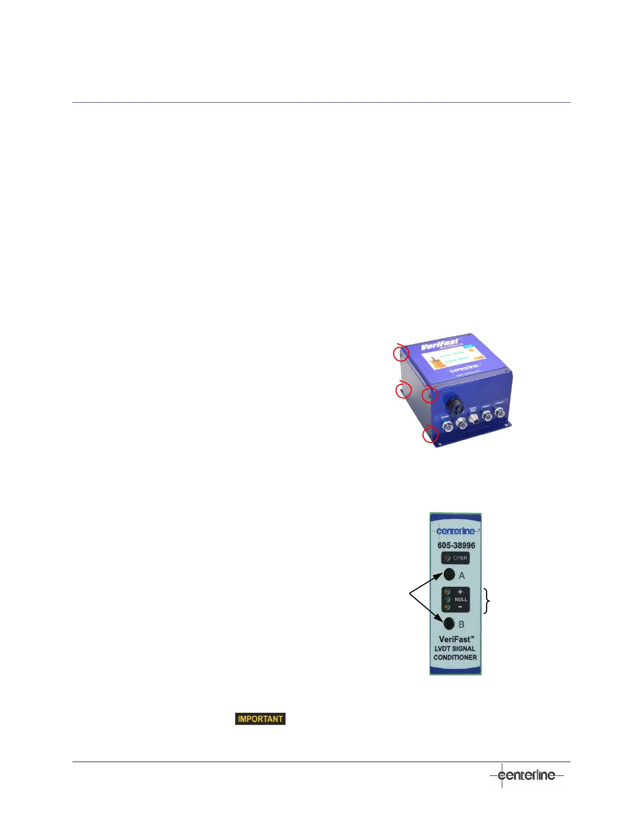
Calibration mode can be cancelled at any time by pressing the buttons 'A' and 'B' (see Figure 8
below) simultaneously for 3 seconds.
In order to re-calibrate the Signal Conditioner, perform the following steps:
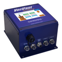
1. Access the Signal Conditioner by removing the
four screws on the left side cover of the
MicroView, as shown in
Figure 7 on the right.
Figure 7 – Accessing the Signal
Conditioner
2. After system power-up, three (3) minutes of warm
up time is recommended.
3. Enter the Calibration Mode by pressing both the
'A' and 'B' buttons (see Figure 8) until the OPER
LED will begin blinking (3 seconds minimum).
4. Move the Pin to its fully extended position and
press the 'B' button. Wait for the Position LEDs to
stop blinking.
5. Move the Pin to its fully retracted position and
press the 'A' button.
If the calibration was successful, the unit will
exit the Calibration Mode and operate with its new
calibration. The OPER LED will be steady ON.
Continue directly with Step 6 below.
If the values after calibration are not as
expected, see the following note and
ignore Step 6.
Figure 8 – LVDT Sensor Display and
Operating Elements
Buttons
Position LEDs
 Loading...