12
VeriFast
TM
MicroView 1.0 – User Manual – Version 1.9
VeriFast™ MicroView Configuration
The three existing configurations of the MicroView controller module are illustrated below, each
with corresponding connection cables.
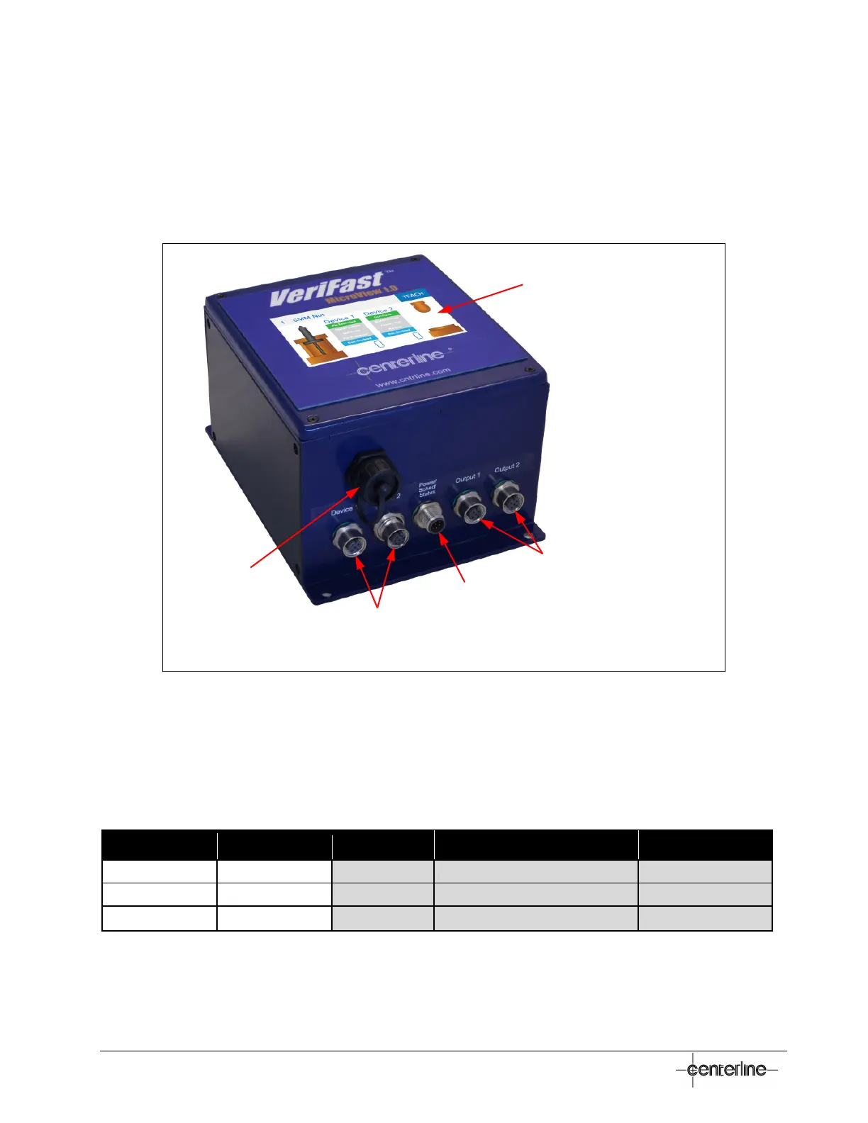
5-port Dual Device Controller and Connection Cables
Figure 1 – Configuration of VeriFast™ MicroView 5-port Dual Device Controller
For the cables required to connect the VeriFast™ MicroView 5-port Dual Device Controller, see
Table 2 below.
Table 2 – Required connection cables for VeriFast™ MicroView 5-port Dual Device
Device 1, Device 2 (input)
Output 1, Output 2 (digital)
** Depends on the configuration of the MicroView.
HMI Display
Output Ports* (Digital)
Power/Schedule/Status Control Port *
Devices Ports* (Inputs)
USB Port
* For cable requirements, see Table 2 below.
 Loading...