Do you have a question about the CenterLine VeriFast MicroView 1.0 and is the answer not in the manual?
Identifies the intended audience for the user manual.
Outlines the manual's objective and scope for the VeriFast™ MicroView controller.
Explains the notations and formatting used throughout the document for clarity.
Defines safety-related terms and symbols used to convey hazards and important information.
Stresses the importance of following all safety considerations for the VeriFast™ MicroView and associated equipment.
Provides guidelines for safe handling of the VeriFast™ MicroView to prevent personal injury.
Details essential lockout procedures before installation, operation, or removal of the MicroView.
Describes the VeriFast™ MicroView 1.0 as a controller for integrating analog position sensors into welding systems.
Lists the technical parameters of the VeriFast™ MicroView 1.0, including power, I/O, and environmental data.
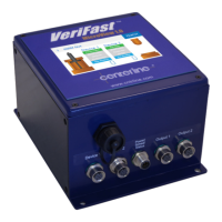
Illustrates the 5-port Dual Device controller and details required connection cables.
Explains the 30 V tolerant PNP digital inputs and their schedule input configurations.
Details the PNP digital outputs, their ratings, and specific output functions like Run Enabled and Teach Enabled.
Guides users on how to find and order replacement components for the MicroView.
Advises users to review general safety information before proceeding with installation.
Provides instructions on how to physically mount the MicroView unit securely.
Offers a specific precaution for connecting the MicroView to field block applications.
Details the pin assignments and functions for the 5-port Dual Device controller's ports.
Provides visual pinout diagrams for various connector types used with the MicroView.
Provides step-by-step instructions for recalibrating the LVDT Signal Conditioner for standard applications.
Illustrates the navigation flow between different screens of the MicroView software interface.
Describes the initial display and the screen saver functionality of the MicroView HMI.
Details how to teach specific positions for LVDT and Laser devices.
Explains how to teach positions for generic devices based on customer-defined parameters.
Recommends reviewing safety information before performing troubleshooting tasks.
Provides instructions for replacing the lithium battery used for the real-time clock.
Provides guidelines for safely removing and storing the MicroView system from service.
| Category | Controller |
|---|---|
| Model | VeriFast MicroView 1.0 |
| Manufacturer | CenterLine |
| Input Voltage | 24 VDC |
| Power Consumption | 10 W |
| Operating Temperature | 0°C to 50°C |
| Storage Temperature | -20°C to 70°C |
| Communication Interface | Ethernet, USB |
| Certifications | CE |