16
VeriFast
TM
MicroView 1.0 – User Manual – Version 1.9
b) P2 – Position 2 – Output is HIGH when the analog signal is within the defined tolerance in
reference to taught nominal position. That is:
i. “Weld Position” – for VeriFast™ LVDT or Laser
ii. “Weld Position” – for LPT
c) P3 – Position 3 – Output is HIGH when the analog signal is within the defined tolerance in
reference to taught nominal position. That is:
i. “Set Down Achieved” – for VeriFast™ LVDT or Laser
ii. “Double Nuts Present” – for LPT
d) P4 – Position 4 – Output is HIGH when the analog signal is within the defined tolerance in
reference to taught nominal position. That is:
iii. “Pin Retracted” – for VeriFast™ LVDT or Laser
iv. “No Nut Present” – for LPT
e) Bypassed – Output is HIGH when the device has been bypassed. Note: This output is
not available for 5-port Single Device configurations.
Analog Inputs
The two 16-Bit analog inputs are designed for 0-10V operation. These inputs are 30 V tolerant and
are wired specifically for the device that is going to be connected to the MicroView. For example, if
the input is configured for a VeriFast™ LVDT, only an LVDT (and not an LPT or analog device)
can be connected to that input.
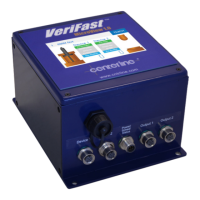
For wiring of your particular MicroView, please refer to the information sticker on the side of the
MicroView enclosure (an example is shown in Figure 4 below).
Figure 4 – Example of Information Sticker Affixed to VeriFast™ MicroView
 Loading...