EasyManua.ls Logo

CenterLine VeriFast MicroView 1.0 - Wiring the Ports of VeriFast MicroView; 5-port Dual Device Port Configuration

CenterLine VeriFast MicroView 1.0
53 pages
Print Icon
To Next Page IconTo Next Page
To Previous Page IconTo Previous Page
Loading...
VeriFast
TM
MicroView 1.0User Manual Version 1.9
19
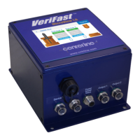
Wiring the Ports of VeriFast™ MicroView
5-port Dual Device Port Configuration
Port on MicroView /
Connected Device
Pin Function
Device 1, Device 2 Ports (Inputs)
VeriFast™ LVDT
1
Primary Coil 1
2
Primary Coil 2
3
Secondary Coil 1
4
Secondary Coil 2
5
Shield
Analog / Laser
1
+24 VDC
2
No Connection
3
0 VDC
4
No Connection
5
0-10 VDC Analog Signal
Balluff LPT
1
No Connection
2
0 VDC
3
No Connection
4
No Connection
5
0-10 VDC Analog Signal
6
Ground (0 VDC)
7
+24 VDC
8
No Connection
Output 1, Output 2 Ports (Digital Outputs)
VeriFast™ LVDT / Analog /
Laser
1
P1 – Pin Extended
2
P2 – Weld Position
3
P3 – Set Down
4
P4 – Pin Retracted
5
P5 – Bypassed
Balluff LPT
1
P1 – Gun Opened
2
P2 – Weld Position
3
P3 – Double Nut
4
P4 – Nut Missing
5
P5 – Bypassed
Power / Schedule / Status Port
VeriFast™ LVDT / Analog /
Laser / Balluff LPT
1
Schedule 1
2
+24 VDC
3
Status Run
4
Schedule 2
5
Schedule 4
6
Schedule 8
7
0 VDC
8
Status Teach

Table of Contents