36
VeriFast
TM
MicroView 1.0 – User Manual – Version 1.9
• – Press this button and a keypad will be displayed, allowing for renaming the
selected schedule.
• Schedule Number – This field identifies the currently selected schedule number. To
navigate through the schedules, use the buttons on the left. Ensure that the desired
schedule remains selected.
• Schedule Name – This field identifies the name of the current schedule (if pre-defined).
The user can navigate between the schedules by using the buttons on the left.
Ensure that the desired schedule remains selected.
• Live Data field displays the instant value corresponding to the live position of the monitored
device. For example, for a VeriFast™ LVDT unit connected to the MicroView as Device 1, this
field will indicate the real time position of the weld pin on the VeriFast™ LVDT unit)
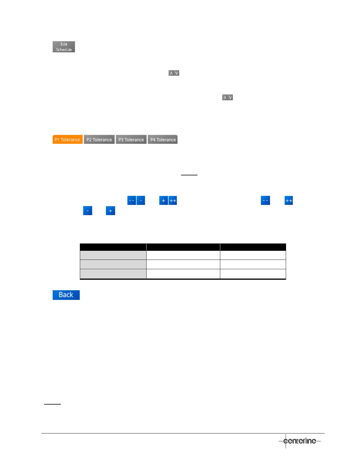
• – Press on the desired button to select
(highlight) the position/status for which the tolerances will be established (P1, P2, P3, or
P4). Ensure that the desired selection remains highlighted.
• Nominal (position value) – This field indicates the already taught value (if any) for the currently
selected position/status (P1, P2, P3, or P4). (Note: This value corresponds to the Nominal
Position Values shown in Figure 13 – Teach Screen on page 31).
• Set Tolerance – The tolerances for each position/status (P1, P2, P3, or P4) are established
(set) on this field. Use the and buttons to adjust the values ( and by
hundreds, and by tens). For minimum and maximum tolerance intervals that can be set
in this field for each type of units, see Table 7 below.
Table 7 – Minimum and Maximum Tolerances for Microview
Counts ± 0 ± 2000
Millimeters ± 0 ± 1.465
Inch ± 0 ± 0.058
• – Press this button to return to the previous menu.
Scaling Screen
The Scaling procedure is used to attune the MicroView unit for accurate measuring in mm or
inches during operation. Without proper scaling, measuring in mm and inches will provide
inaccurate readings during operation. Using counts during operation does not require scaling.
The MicroView must be scaled at the initial setup, and subsequently whenever a device is
connected to the MicroView unit.
Scaling must be done individually for each device connected to the MicroView using any of the
given measuring units (mm or inch).
(Note: The Scaling screen is accessible from the Maintenance Settings Screen (see page 34
)).
 Loading...