VeriFast
TM
MicroView 1.0 – User Manual – Version 1.9
11
Equipment and Process Overview
Intended Use of Equipment
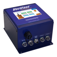
The VeriFast™ MicroView 1.0 is a stand-alone controller that allows simple integration of analog
linear position sensing devices into resistance welding systems that require digital I/O.
The VeriFast™ MicroView 1.0 is available in three configurations:
• VeriFast™ MicroView 5-port Dual Device – can integrate up to two (2) of the following
devices:
VeriFast™ LPT
Generic device that operates on 0 to 10 V
• VeriFast™ MicroView 10-port Dual Device – can integrate up to two (2) of the devices
listed above.
• VeriFast™ MicroView 5-port Single Device – can integrate only one VeriFast™ LVDT.
No other devices can be integrated with this configuration.
Regardless of configuration, each device must be connected to a channel on the MicroView
controller. For each channel, the user can teach 15 schedules. Every schedule can monitor up to
four (4) linear positions, with a set of independent upper/lower tolerance window that can be
individually set for each position.
The MicroView can output four (4) digital outputs per channel. These digital outputs are controlled
by a nominal position, with tolerances taken into account. When the analog signal is within the
window, the corresponding digital output is HIGH.
In addition to the four digital outputs per channel, each channel has a digital output signal
indicating if the device has been bypassed (Bypassed is logic HIGH).
The On-board storage has the ability to store up to 500,000 points of data per input device.
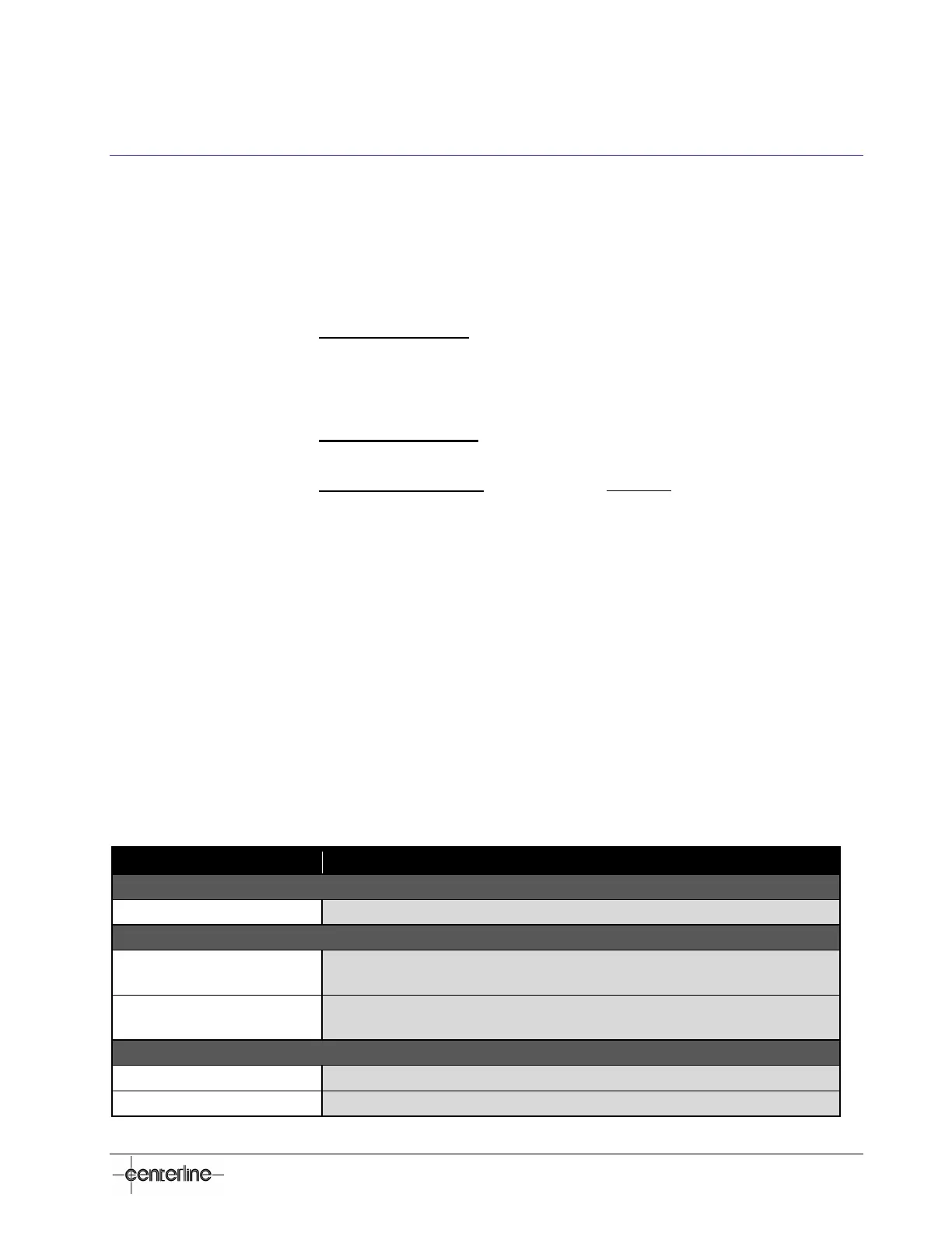
Technical Specifications
Table 1 – Technical Specifications of VeriFast™ MicroView 1.0
18 VDC – 30 VDC, 1 A max @ 24 VDC
Input
PNP, High True
V
IL
= 2.4 VDC Max., I
IL
= 3.0 mA Max., V
IH
= 30 VDC Max.
Output
PNP, Low True
V
OL
= 0.8 VDC Max., I
OL
= 50 mA Max., V
OH
= 30 VDC Max.
Operating Temperature Range
150 mm x 220 mm x 110 mm (5-7/8 in. x 8-5/8 in. x 4-1/4 in) (Width x Height x Depth)
 Loading...