VeriFast
TM
MicroView 1.0 – User Manual – Version 1.9
15
Description of I/O
Digital Inputs
The VeriFast™ MicroView digital inputs are 30 V tolerant PNP inputs. For a 24 V input, the
maximum current drawn will be less than 1 mA.
• Schedule Inputs (4 Bits)
a) Binary 1
b) Binary 2
c) Binary 4
d) Binary 8
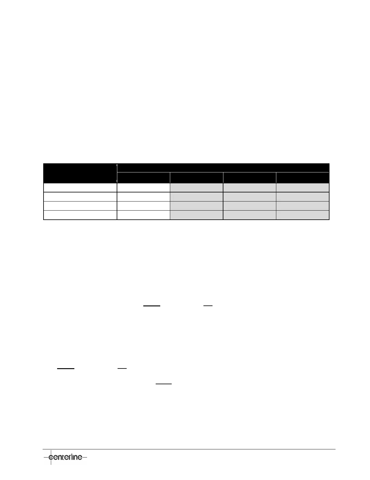
Table 5 – Minimum Pin Configuration
Number of Schedules
Required
Digital Outputs
The VeriFast™ MicroView digital outputs are PNP outputs and source the voltage present on the
VIN to the device. The digital outputs are solid state driven, with a 10 million cycle rating, and a
maximum current output rating of 100 mA. If draw exceeds 100 mA, a resettable fuse is triggered.
If this happens, it takes approximately 2~5 minutes for the fuse to reset. Each output has
independent fuses, so if one is tripped, the others are still active.
1. Run Enabled – Logic HIGH when device is in an active run state. Active LOW when device is
in a maintenance teach state. Note: This output is not available for 5-port Single Device
configurations.
2. Teach Enabled – Logic HIGH when device is:
a) in a maintenance teach mode
b) in a running teach mode
c) when teach mode is requested.
Note: This output is not available for 5-port Single Device configurations.
3. Outputs for both channel 1 & 2 (Note: Position outputs are only active if there is a schedule
selected (i.e., schedule inputs not zero) and in Run Mode):
a) P1 – Position 1 – Output is HIGH when the analog signal is within the defined tolerance in
reference to taught nominal position. That is:
i. “Pin Extended” – for VeriFast™ LVDT or Laser
ii. “Gun Open” – for LPT
 Loading...