Electrical Safety Analyzer 19032 User’s Manual
4-20
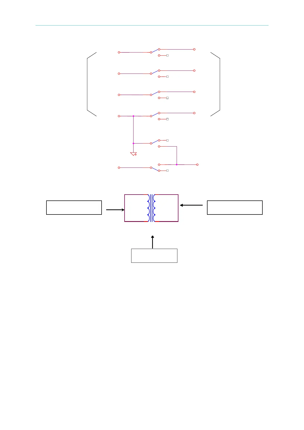
Example:
(1) P – S: Sets CHANNEL 3 to L.
(2) P – G: Sets CHANNEL 3 to X.
(3) (P+S) – G: Sets CHANNEL 3 to H.
Or scanning test selection point (use with optional device, for example: 6000-03)
Withstanding Voltage Test Mode (DC)
VOLTAGE : Sets the voltage for the withstanding voltage test.
HIGH LIMIT : Sets the leakage current high limit value.
LOW LIMIT : Sets the leakage current low limit value. The range is ≤ leakage current
high limit value or OFF.
DWELL TIME: Sets the DWELL time. (0=OFF). (Do not read the high and low limit values of
leakage current during the DWELL TIME. The limitation is not over 1.5
times the high limit range or high limit of leakage current.)
ARC LIMIT : Sets the arc current high limit value.
ARC FILTER : Selects the frequency range of detection arc. Four ranges can be selected:
3∼23 kHz / 3∼50 kHz / 3∼100 kHz / 3∼230 kHz.
(TEST TIME : Sets the test duration time. (0=CONTINUOUS).
RAMP TIME
: Sets the ramp time. (0=OFF).