Descriptions of Panel
4-33
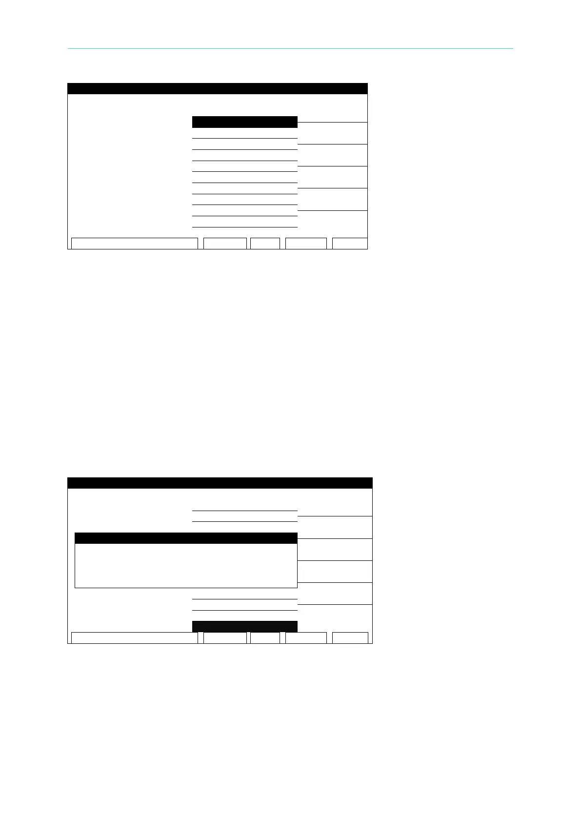
Figure 4-20
Set the following parameters as required by the test:
01. TEST STEP: Select the number of the test step to set the parameters for.
02. TEST MODE: Select the (AC) test mode
03. VOLTAGE: Set the required voltage - 0.05 - 5KV
04. AC FREQ.: Set the require frequency – 50 - 600Hz (0=DEFAULT)
05. HIGH LIMIT: Set the high limit - 0.001 - 40mA
06. LOW LI MIT: Set the low limit – 0 - 40mA (0 = OFF)
07. ARC LIMIT: Set the arc limit – 1 -30 mA (0 = OFF)
08. ARC FILTER: Select the filter range (3-23kHZ / 3-50kHZ / 3-100kHZ / 3-230kHZ)
09. TEST TIME: Set the test duration time - 0.3 – 999 Sec (0 = CONTINUOUS)
10. RAMP TIME: Set the ramp time – 0 – 999 Sec (0 = OFF)
11. FALL TIME : Set the fall time – 0 – 999 Sec (0=OFF)
12. CHNL (H-L): Press the (SETUP) Function Key
Press the [SETUP] Function Key to enter the SETUP SCANNER-1 menu:
Figure 4-21
Press the numeric Key [3] repeatedly to select H, L, or X.
H: The HV OUTPUT on both the front and rear panels are ON.
L: The HV OUTPUT on the rear panel and the DRIVE- on front panel are short grounded. The
DRIVE- on the rear panel is floating.
X: The HV OUTPUT on both the front and rear panels are open circuit. GB terminals on the
front and rear panels are ON.