-10V 0V 10V
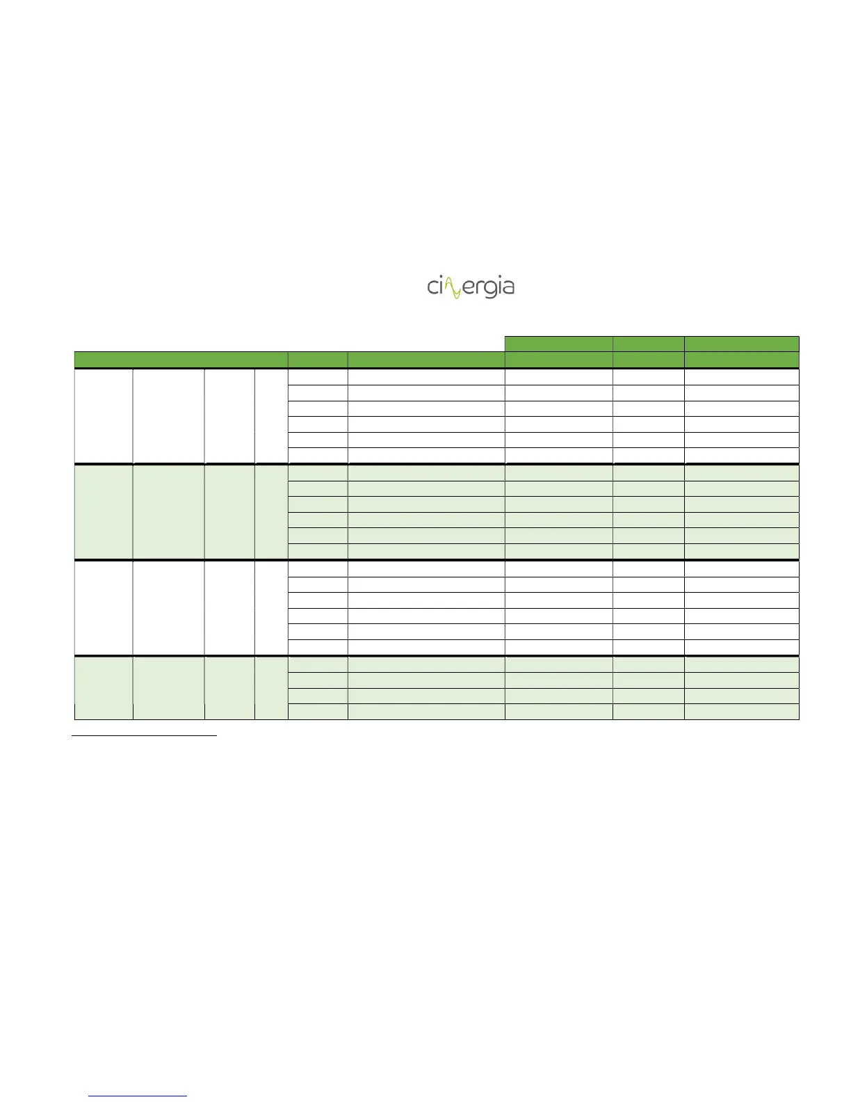
MODE ANALOG VARIABLE MINIMUM MEDIUM MAXIMUM
Voltage
source
Independent Bipolar AC
U1 Voltage U RMS setpoint not used 0 max voltage AC
U2 Voltage Phase angle U
2
-359º 0 359º
V1 Voltage V RMS setpoint not used 0 max voltage AC
V2 Voltage Phase angle V -359º -120º -120º 359º -120º
W1 Voltage W RMS setpoint not used 0 max voltage AC
W2 Voltage Phase angle W -359º -240º -240º 359º -240º
Current
source
Independent Bipolar AC
U1 Current U RMS setpoint min current AC 0 max current AC
U2 Phase angle U -90º 0 90º
V1 Current V RMS setpoint min current AC 0 max current AC
V2 Phase angle V -90º 0 90º
W1 Current W RMS setpoint min current AC 0 max current AC
W2 Phase angle W -90º 0 90º
Power
source
Independent Bipolar AC
U1 Active power U min power 0 max power
U2 Reactive power U min power 0 max power
V1 Active power V min power 0 max power
V2 Reactive power V min power 0 max power
W1 Active power W min power 0 max power
W2 Reactive power W min power 0 max power
Impedance
Independent Bipolar AC
U1 Resistance U not used 10000 0
U2 Inductance U not used 10000 0
V1 Resistance V not used 10000 0
V2 Inductance V not used 10000 0
2
In case of generate a triphase grid, it is need to send a 0, -120º, -240º on SP Voltage Phase angle U/V/W.