Note: The ratio is between the primary and the secondary.
4.10.3.7.2. Neutral current transformation ratios (CVM-C10-ITF-IN).
Table 29:Modbus memory map: Neutral current transformation ratios.
Transformation ratios
Configuration variable
(1)
Address Valid data margin
Default
value
Neutral current primary 271A 1 - 10000 5
Neutral current secondary 271B
1: .../1A
5: ../5 A
5
(1)
All variables must be programmed at the same time.
4.10.3.7.3. Number of quadrants
Table 30:Modbus memory map: Number of quadrants
Maximum demand
Configuration variable Address Valid data margin
Default
value
Number of quadrants 2B64
0: 4 quadrants
1: 2 quadrants
0
4.10.3.7.4.Measurement convention
Table 31:Modbus memory map: Measurement convention.
Measurement convention
Configuration variable Address Valid data margin Default value
Measurement convention 2B86
0: Circutor
1: IEC
2: IEEE
0
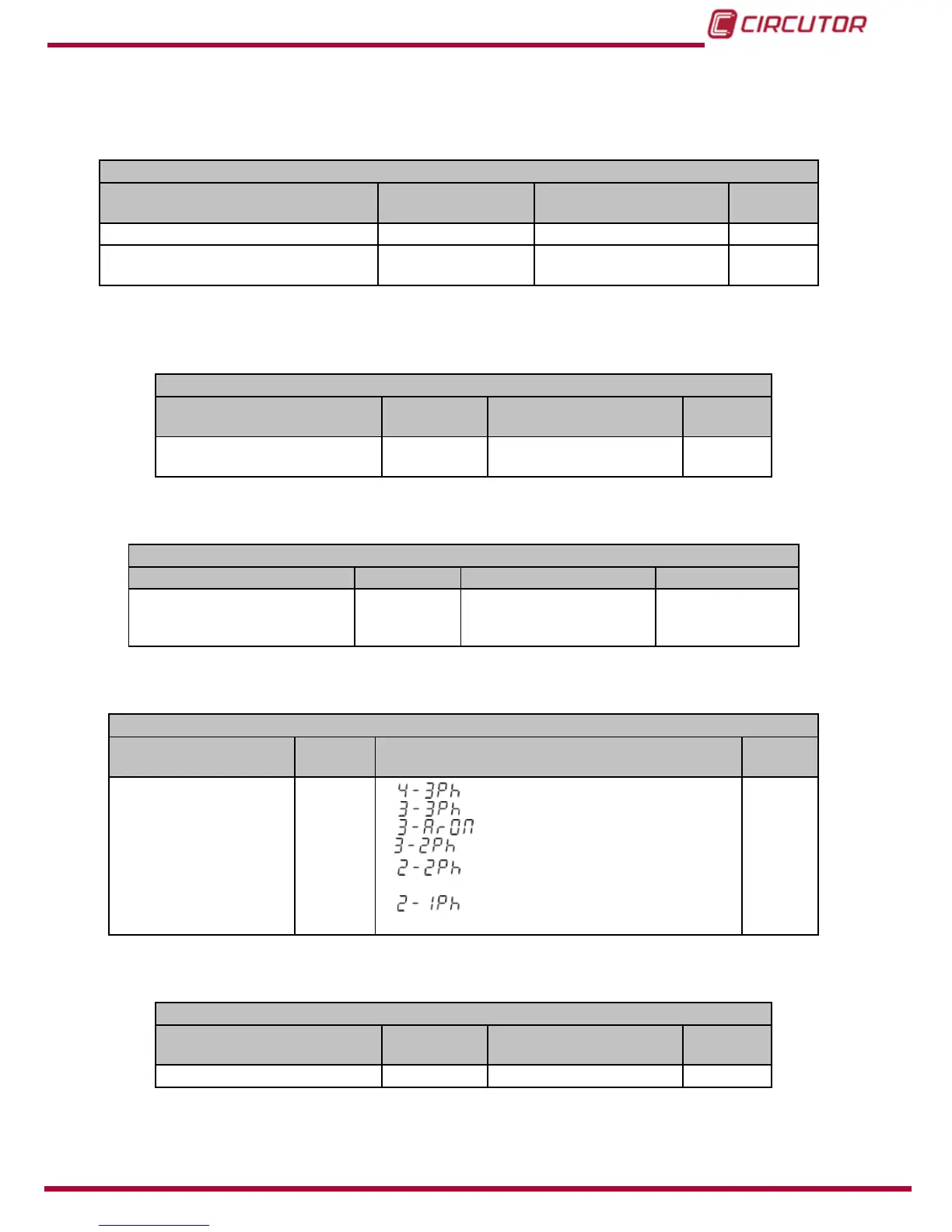
4.10.3.7.5. Type of installation
Table 32:Modbus memory map: Type of installation
Type of installation
Configuration variable Address Valid data margin
Default
value
Type of installation 2B5C
0:
Three-phase network with 4 wires.
1:
Three-phase network with 3 wires.
2:
Three-phase network with 3 wires, Aron.
3:
Two-phase network with 3 wires.
4:
Single-phase network with 2 wires, phase-
to-phase.
5:
Single-phase network with 2 wires, phase-
to-neutral.
0
4.10.3.7.6. Maximum demand
Table 33:Modbus memory map: Maximum demand
Maximum demand
Configuration variable Address Valid data margin
Default
value
Integration period 274C 1 - 60 minutes 15
79