5-51
Hardware Installation Guide for Cisco 4000 Series Integrated Services Routers
OL-32185-02
Chapter 5 Install and Upgrade Internal Modules and FRUs
Remove and Replace Cisco 4000 Series ISRs Power Supplies
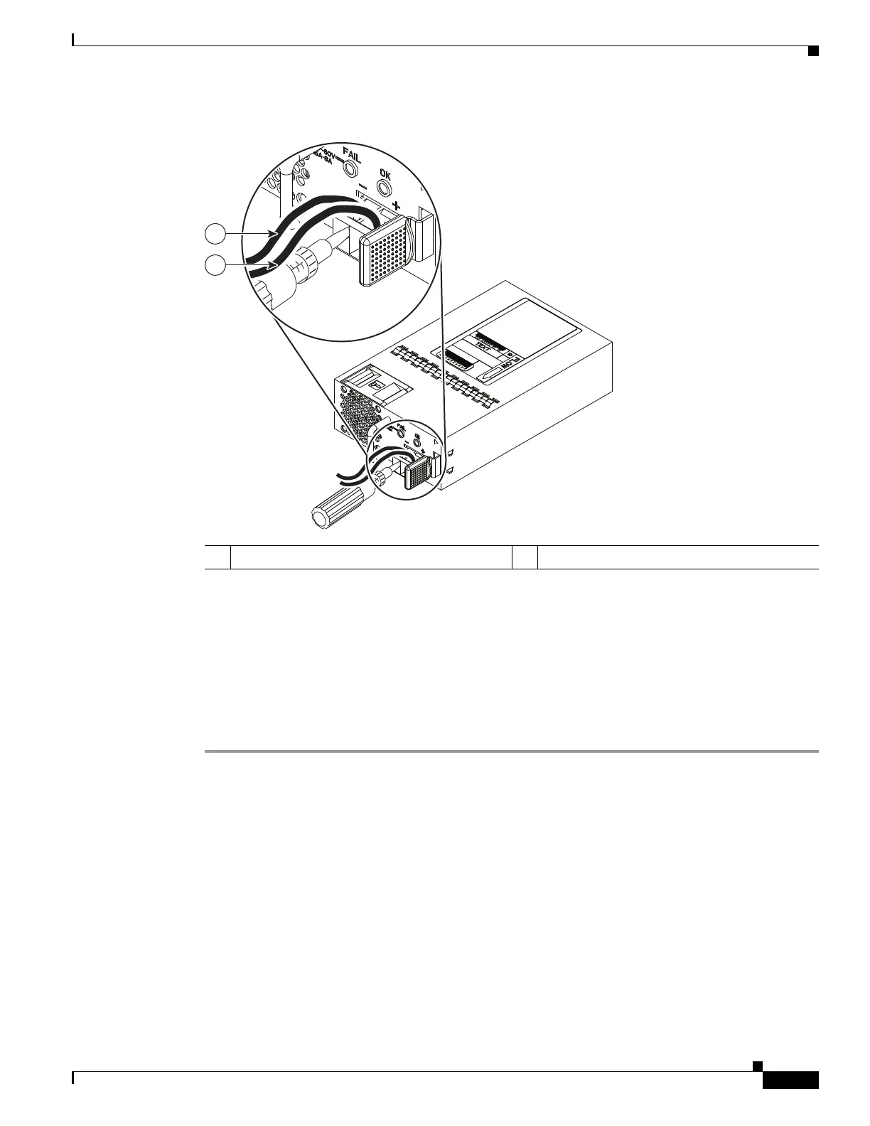
Figure 5-40 DC Power Supply with Lead Wires
Step 9
Repeat these steps for the remaining DC input power source wire as applicable.
Step 10 Use a tie wrap to secure the wires to the rack, so that the wires are not pulled from the terminal block by
casual contact.
Step 11 Turn on the circuit breaker at the power source.
Step 12 If you have changed the standby switch to the standby position in Step 1, turn the standby switch to the
On position.
The power supply LEDs illuminate green.
1 Negative (–) lead wire 2 Positive (+) lead wire
372766
1
2

 Loading...


