5-58
Hardware Installation Guide for Cisco 4000 Series Integrated Services Routers
OL-32185-02
Chapter 5 Install and Upgrade Internal Modules and FRUs
PoE Converter Power Supply Unit
Remove PoE Power Supply Slot Filler
Step 1 Remove the bezel and fan tray from the router.
Step 2 Loosen the screws from the securing nuts on the chassis. See Figure 5-46 for details.
Step 3 Gently pull out the filler from the filler tab on the chassis.
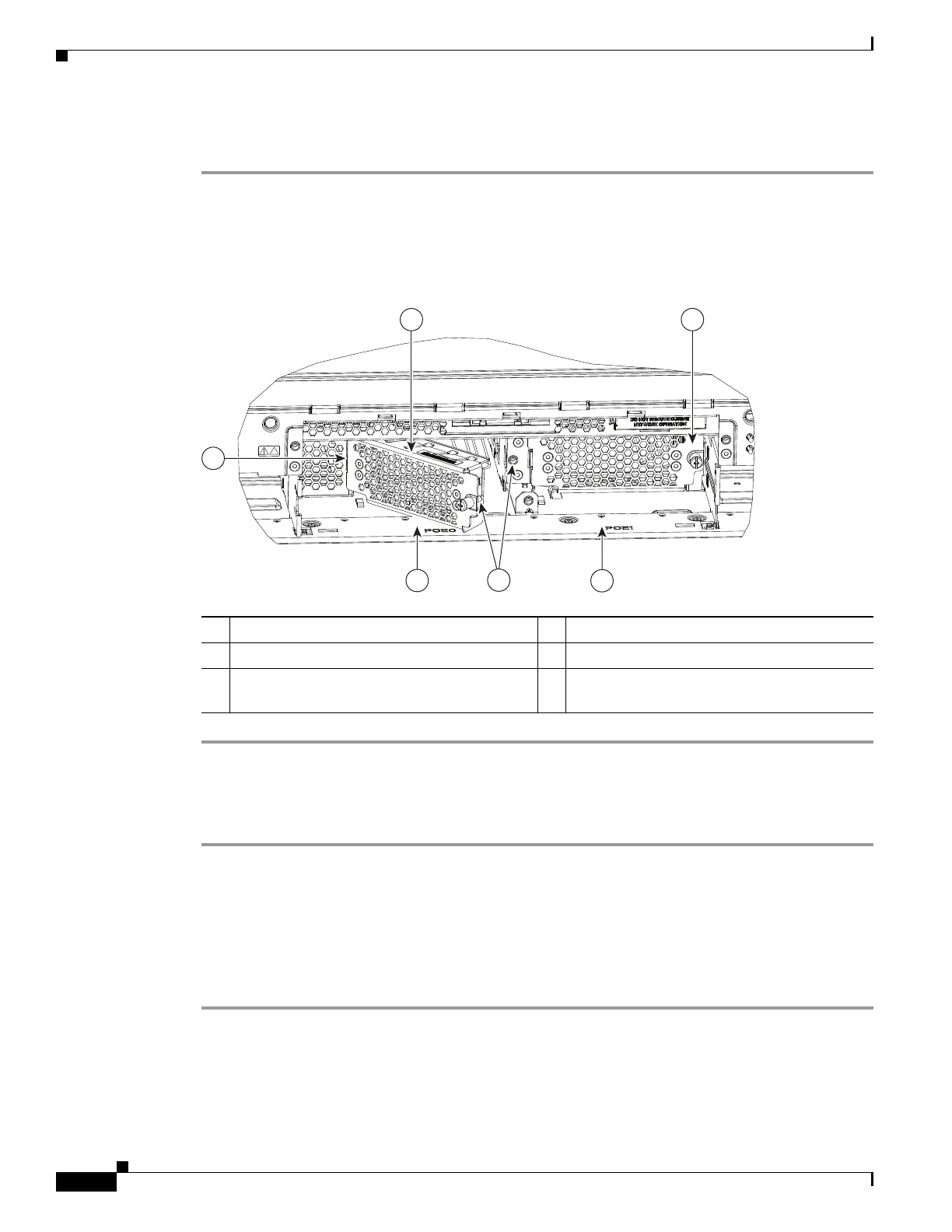
Figure 5-46 Install or Remove PoE Fillers
Install the PoE Converter Power Supply
Step 1 Remove the bezel and fan try from the router chassis. See Replace Fan Tray, page 5-61.
Step 2 Remove the PoE converter power supply filler. For instructions, see “Remove PoE Power Supply Slot
Filler”.
Step 3 Open the slot latch before inserting the PoE converter power supply module.
Step 4 Rotate latch to close it.
Step 5 Tighten the screws on the module to secure it to the router chassis.See Figure 5-47 for details.
2
1
6 4
5
3
391819
1 Install tab into slot on chassis 2 POE filler being installed in PoE slot 0
3 PoE filler shown installed in PoE slot 1 4 PoE slot 1
5 Rotate to secure screw into securing nut in
chassis
6 PoE slot 0

 Loading...


