EasyManuals Logo

Cisco 4000 Series User Manual

Cisco 4000 Series
206 pages
To Next Page IconTo Next Page
To Previous Page IconTo Previous Page
Page #174 background imageLoading...
Page #174 background image
5-50
Hardware Installation Guide for Cisco 4000 Series Integrated Services Routers
OL-32185-02
Chapter 5 Install and Upgrade Internal Modules and FRUs
Remove and Replace Cisco 4000 Series ISRs Power Supplies
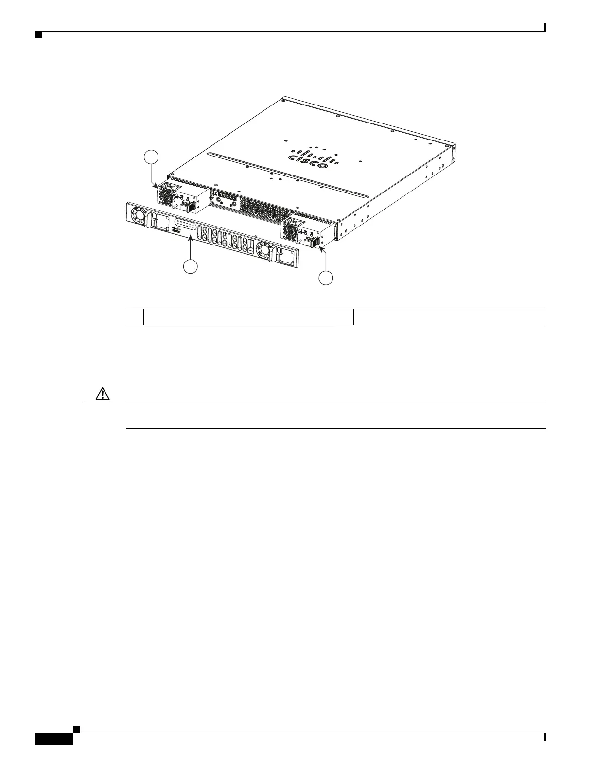
Figure 5-39 Remove the Bezel
Step 6 Insert the wires through the holes in the bezel. Replace the bezel.
Step 7 Insert the exposed wire into the terminal block. Ensure that the wire lead is not placed outside the plastic
cover. Only wires with insulation should extend from the terminal block.
Caution Do not overtorque the terminal block captive screws. Ensure that the connection is snug, but the wire is
not crushed. Verify by tugging lightly on each wire to ensure that they do not move.
Step 8 Use a screwdriver to tighten the terminal block captive screws, as shown in Figure 5-40.
1 Bezel 2 DC power supplies
391892
1
2
2

Table of Contents

Other manuals for Cisco 4000 Series

Questions and Answers:

Question and Answer IconNeed help?

Do you have a question about the Cisco 4000 Series and is the answer not in the manual?

Cisco 4000 Series Specifications

General IconGeneral
CategoryNetwork Router
Product TypeRouter
Form FactorRack-mountable
Connectivity TechnologyWired
Product FamilyCisco 4000 Series
Operating SystemCisco IOS XE
DimensionsVaries by model
WeightVaries by model
ModelCisco 4000 Series
WAN PortsVaries by model
LAN PortsVaries by model
StorageVaries by model
RedundancyVaries by model
Security FeaturesVaries by model
Network ManagementVaries by model
Data Link ProtocolEthernet, Fast Ethernet, Gigabit Ethernet
Network/Transport ProtocolTCP/IP, UDP
FeaturesVaries by model
InterfacesVaries by model
ModelsVaries
Network InterfacesVaries by model
Power SupplyVaries by model
Virtualization SupportYes

Related product manuals