5-49
Hardware Installation Guide for Cisco 4000 Series Integrated Services Routers
OL-32185-02
Chapter 5 Install and Upgrade Internal Modules and FRUs
Remove and Replace Cisco 4000 Series ISRs Power Supplies
Note You do not require to place the power switch in the standby position if you want to hot-swap a
single power supply.
Step 2 Insert the power supply in the power-supply slot, and gently push it into the slot. When correctly
installed:
• For Cisco 4431 ISR, the DC power supply (excluding the extraction handle) is flush with the router.
• For Cisco 4451 ISR and Cisco 4351ISR, the DC power supply (excluding the extraction handle) is
recessed from the router bezel.
Step 3 Wire can be stripped and terminated directly to the power supply terminal block, or a crimp style spade
terminal lug can be used. If you are using a terminal lug, follow the manufacturer's instructions for
terminating the lug to the wire. If terminating directly to the terminal block using bare wire, follow the
instructions in the Figure 5-40. Use a wire-stripping tool to strip each of the two wires coming from the
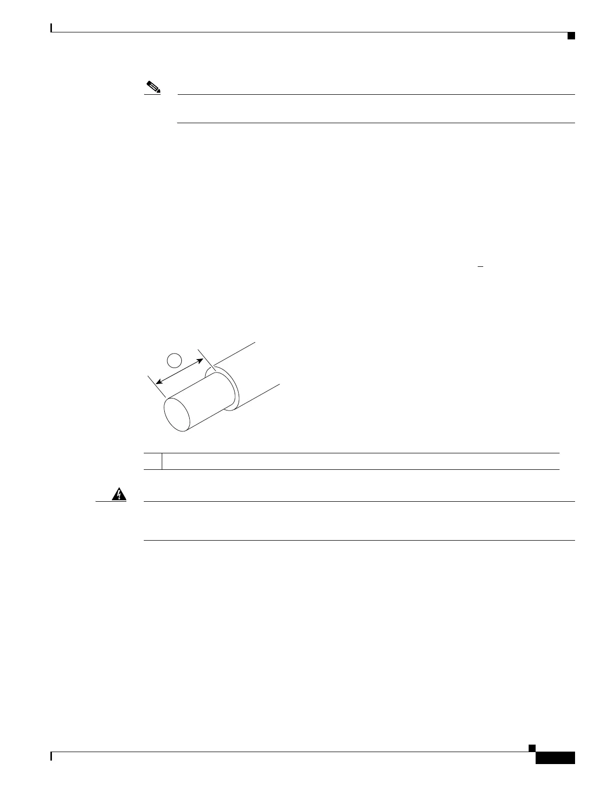
DC input power source and strip the wires to approximately 0.39 inch (10 mm) +
0.02 inch (0.5 mm).
We recommend that you use 14 AWG insulated wire. Do not strip more than the recommended length of
wire because doing so could leave the wire exposed from the terminal block. Figure 5-38 shows a
stripped DC input power source wire.
Figure 5-38 Stripped DC Input Power Source Wire
Warning
An exposed wire lead from a DC input power source can conduct harmful levels of electricity. Be sure
that no exposed portion of the DC input power source wire extends from the terminal block.
Statement
122
Step 4 Identify the positive and negative feed positions for the terminal block connection. The wiring sequence
is:
1. Positive (+) lead wire (right)
2. Negative (–) lead wire (left)
Step 5 Remove the router bezel. See Figure 5-39. The bezel is secured with snap latches. To remove the bezel,
hold the top and bottom and pull the bezel.
1 0.39 inch (10 mm) is the recommended wire-strip length for the terminal block.

 Loading...


