1-10
Hardware Installation Guide for the Cisco 4000 Series Integrated Services Router
OL-32185-02
Chapter 1 Overview of Cisco 4000 Series ISRs
Chassis Views
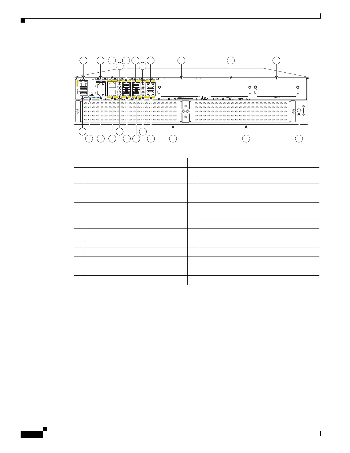
Figure 1-8 Back Panel (I/O Side) Slots and Connectors on Cisco 4451-X ISR
1 GE 0 management port 2 Auxiliary port
3 RJ-45 Gigabit Ethernet port (GE 0/0/0) 4 LEDs for the GE 0/0/0 interface (See Table 1-1
for detailed LED information)
5 SFP/Gigabit Ethernet port (GE 0/0/0) 6 SFP/Gigabit Ethernet port (GE 0/0/2)
7 LEDs for the GE 0/0/2 interface 8 RJ-45 Gigabit Ethernet port (GE 0/0/2)
9 NIM slot 1 (shown with slot divider
removed).
10 NIM slot 2 (shown with slot divider removed).
11 NIM slot 3 12 Ground connection
13 Enhanced Service Module (SM-X) 2 14 Enhanced Service Module (SM-X) 1
15 RJ-45 Gigabit Ethernet port GE 0/0/3 16 LEDs for the GE 0/0/3 interface
17 SFP/Gigabit Ethernet GE 0/0/3 18 SFP Gigabit Ethernet GE 0/0/1
19 LEDs for the GE 0/0/1 interface 20 RJ-45 Gigabit Ethernet port GE 0/0/1
21 Serial console port 22 USB Type B mini port
23 USB 0 and USB 1
2
1
285698
1 2 3 5 6 8 9 10 11
4 7
13 12
14
1923 16
18 17 15
21 2022

 Loading...


