2-7
Catalyst 6500 Series Switch SIP, SSC, and SPA Hardware Installation Guide
OL-9041-04
Chapter 2 Catalyst 6500 Series Switch SIPs and SSCs Overview
Cisco 7600 SIP-200 Overview
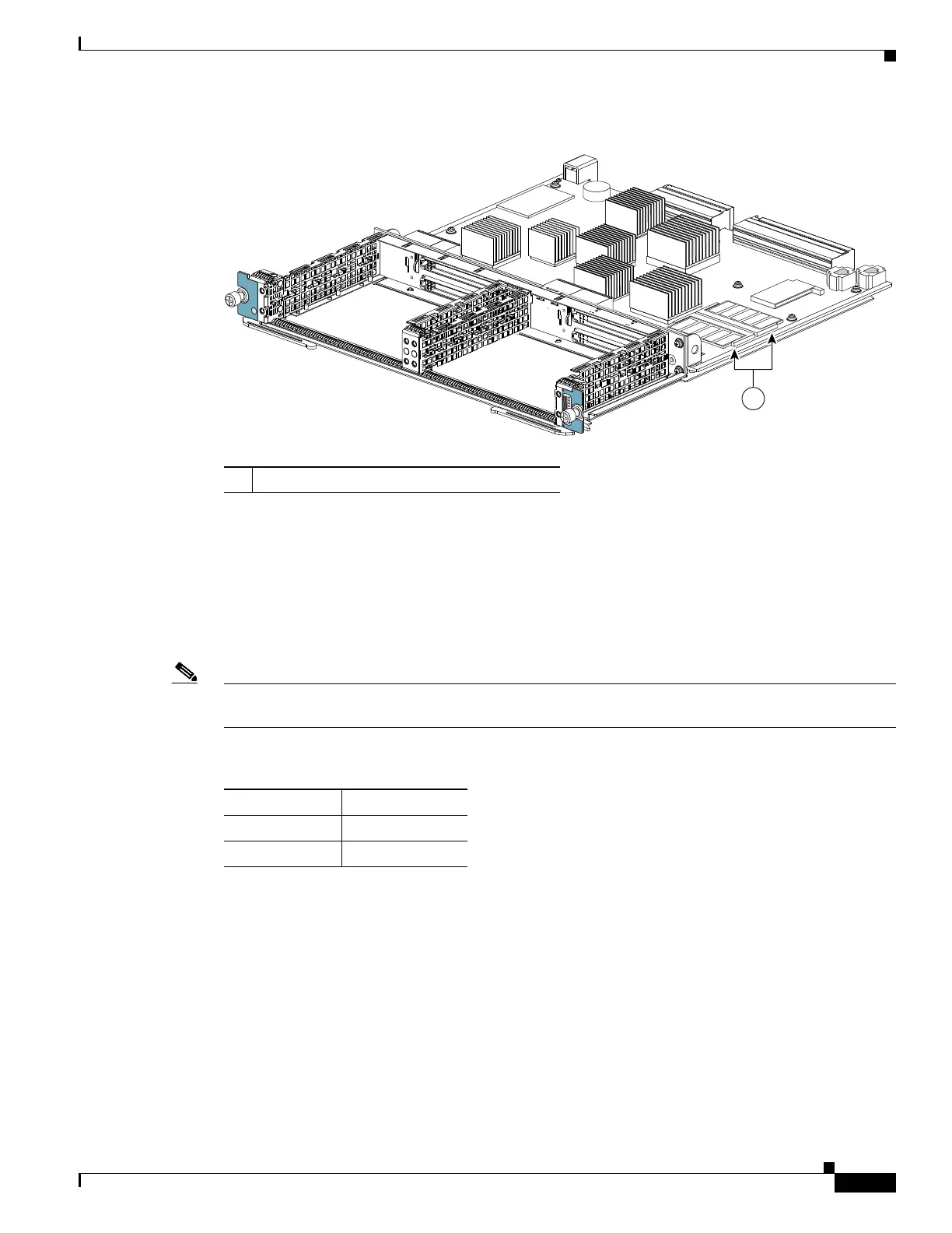
Figure 2-4 SIP DIMM Location
Cisco 7600 SIP-200 Default DIP Switch Settings
If SW3 and SW10 switches are present on the board, make sure that they are set to the default settings,
as shown in
Table 2-6. See Figure 2-5 for the location of the switches.
The switches are set to their defaults during manufacture. However, the switch settings may get
inadvertently changed during handling.
Note If the switches are not set to their default settings, there may be momentary packet drops during OIR of
the board.
1 DIMMs
STATUS
2
0
MODULAR
SERVICES CARD
7
60
0
-M
S
C
-2
00
122390
1
Ta b l e 2-6 7600-SIP-200 Default DIP Settings
Switch Default Position
SW3 Up
SW10 Down
 Loading...


