3-10
Catalyst 6500 Series Switch SIP, SSC, and SPA Hardware Installation Guide
OL-9041-04
Chapter 3 Catalyst 6500 Series Switch SPA Overview
1-Port Channelized STM-1/OC-3 SPA Overview
8-Port Channelized T1/E1 SPA Cables, Connectors, and Pinouts
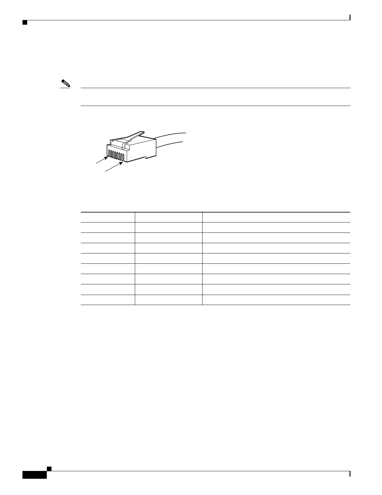
Figure 3-4 shows an RJ-45 connector.
Note The terms RJ-45 and RJ-48c are sometimes used interchangeably. The RJ-48c is the jack or receptacle;
the RJ-45 is the connector.
Figure 3-4 RJ-45 Connector
Table 3-8 describes the signals and connector pinouts for RJ-45 cable connectors.
1-Port Channelized STM-1/OC-3 SPA Overview
The following sections describe the 1-Port Channelized STM-1/OC-3 SPA:
• 1-Port Channelized STM-1/OC-3 SPA LEDs, page 3-10
• 1-Port Channelized STM-1/OC-3 SPA Interface Specifications, page 3-11
• 1-Port Channelized STM-1/OC-3 SPA Cables and Connectors, page 3-12
1-Port Channelized STM-1/OC-3 SPA LEDs
The 1-Port Channelized STM-1/OC-3 SPA has two types of LEDs: an A/L LED for each port and a
STATUS LED, as shown in
Figure 3-5.
32770
RJ-45
RJ-48c
Pin 1
Pin 8
Ta b l e 3-8 RJ-45 Connector Pinouts
Pin Signal Description
1 RX– Receive ring –
2 RX+ Receive tip +
3 NC No connection
4 TX– Transmit ring –
5 TX+ Transmit tip +
6 NC No connection
7 NC No connection
8 NC No connection
 Loading...


