3-54
Catalyst 6500 Series Switch SIP, SSC, and SPA Hardware Installation Guide
OL-9041-04
Chapter 3 Catalyst 6500 Series Switch SPA Overview
10-Port Gigabit Ethernet SPA Overview
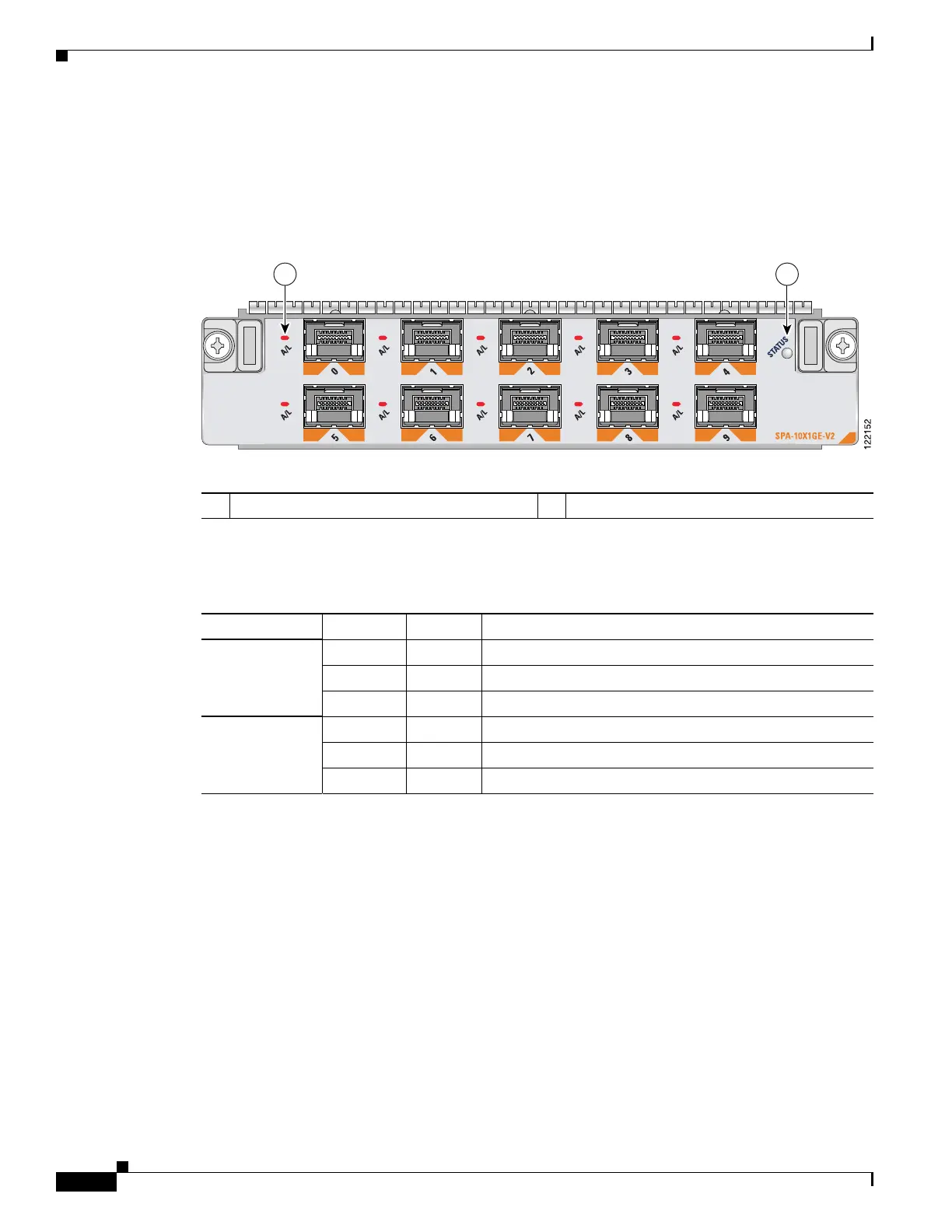
10-Port Gigabit Ethernet SPA LEDs
The 10-Port Gigabit Ethernet SPA has two types of LEDs: an A/L LED for each individual port and a
STATUS LED for the SPA, as shown in
Figure 3-41.
Figure 3-41 10-Port Gigabit Ethernet SPA Faceplate
Table 3-34 describes the 10-Port Gigabit Ethernet SPA LEDs.
10-Port Gigabit Ethernet SPA Cables and Connectors
The 10-Port Gigabit Ethernet SPA has ten electrical connectors that support SFP modules. Each port can
send and receive traffic using cabling appropriate for the SFP module inserted.
SFP Module Connections
The small form-factor pluggable (SFP) module is an input/output (I/O) device that plugs into the Gigabit
Ethernet optical slots on the 10-Port Gigabit Ethernet SPA, linking the port with a 1000BASE-X
fiber-optic network.
1 A/L (Active/Link) LED 2 STATUS LED
Ta b l e 3-34 10-Port Gigabit Ethernet SPA LEDs
LED Label Color State Meaning
A/L Off Off Port is not enabled.
Green On Port is enabled and the link is up.
Amber On Port is enabled and the link is down.
STATUS Off Off SPA power is off.
Green On SPA is ready and operational.
Amber On SPA power is on and the SPA is being configured.
 Loading...


