11-8
Catalyst 6500 Series Content Switching Module Configuration Note
OL-4612-01
Chapter 11 Configuring Firewall Load Balancing
Configuring Stealth Firewall Load Balancing
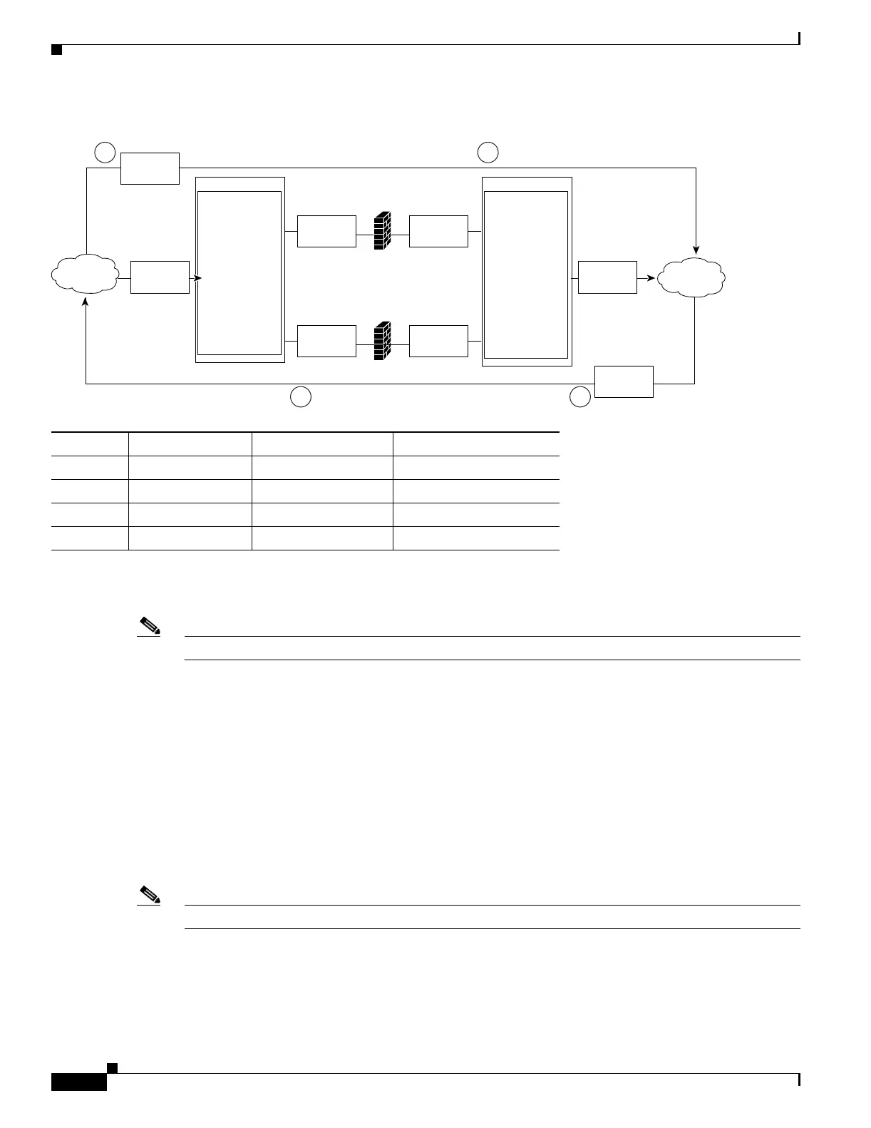
Figure 11-6 Stealth Firewall Configuration Example
Figure 11-6 shows two regular firewalls (Firewall 1 and Firewall 2) sandwiched between two CSMs
(CSM A and CSM B).
Note Stealth firewalls do not have addresses on VLANs.
On the path from the Internet to the intranet, traffic enters the insecure side of the firewalls through
separate VLANs, VLAN 101 and VLAN 103, and exits the secure side of the firewalls through separate
VLANs, VLAN 102 and VLAN 104. On the path from the intranet to the Internet, the flow is reversed.
VLANs also provide connectivity to the Internet (VLAN 10) and to the intranet (VLAN 20).
In a stealth configuration, CSM A and CSM B load balance traffic through the firewalls.
Stealth Firewall Configuration Example
The stealth firewall configuration example contains two CSMs (CSM A and CSM B) installed in separate
Catalyst 6500 series switches.
Note In a stealth firewall configuration, each CSM must be installed in a separate Catalyst 6500 series switch.
This section describes how to create the stealth firewall configuration for CSM A and CSM B.
Location Traffic Direction Arrives On Exits On
1 To intranet VLAN 10 VLANs 101 and 103
2 To intranet VLANs 101 and 103 VLAN 20
3 To Internet VLAN 20 VLANs 102 and 104
4 To Internet VLANs 101 and 103 VLAN 10
VLAN 10 VLAN 20
Catalyst 6500
CSM-A
IP address
10.0.101.35
IP address
10.0.101.36
IP address
10.0.102.36
IP address
10.1.0.200
IP address
10.0.102.35
IP address
10.0.1.35
IP address
10.0.1.36
Catalyst 6500
CSM-B
Internet
63909
Intranet
10.1.0.x
VLAN 101
VLAN 103
VLAN 102
Firewall 1
Firewall 2
VLAN 104
Traffic to
Intranet
Traffic to
Internet
1 2
34
 Loading...


