2-6
Catalyst 6500 Series Content Switching Module Configuration Note
OL-4612-01
Chapter 2 Networking with the Content Switching Module
CSM Networking Topologies
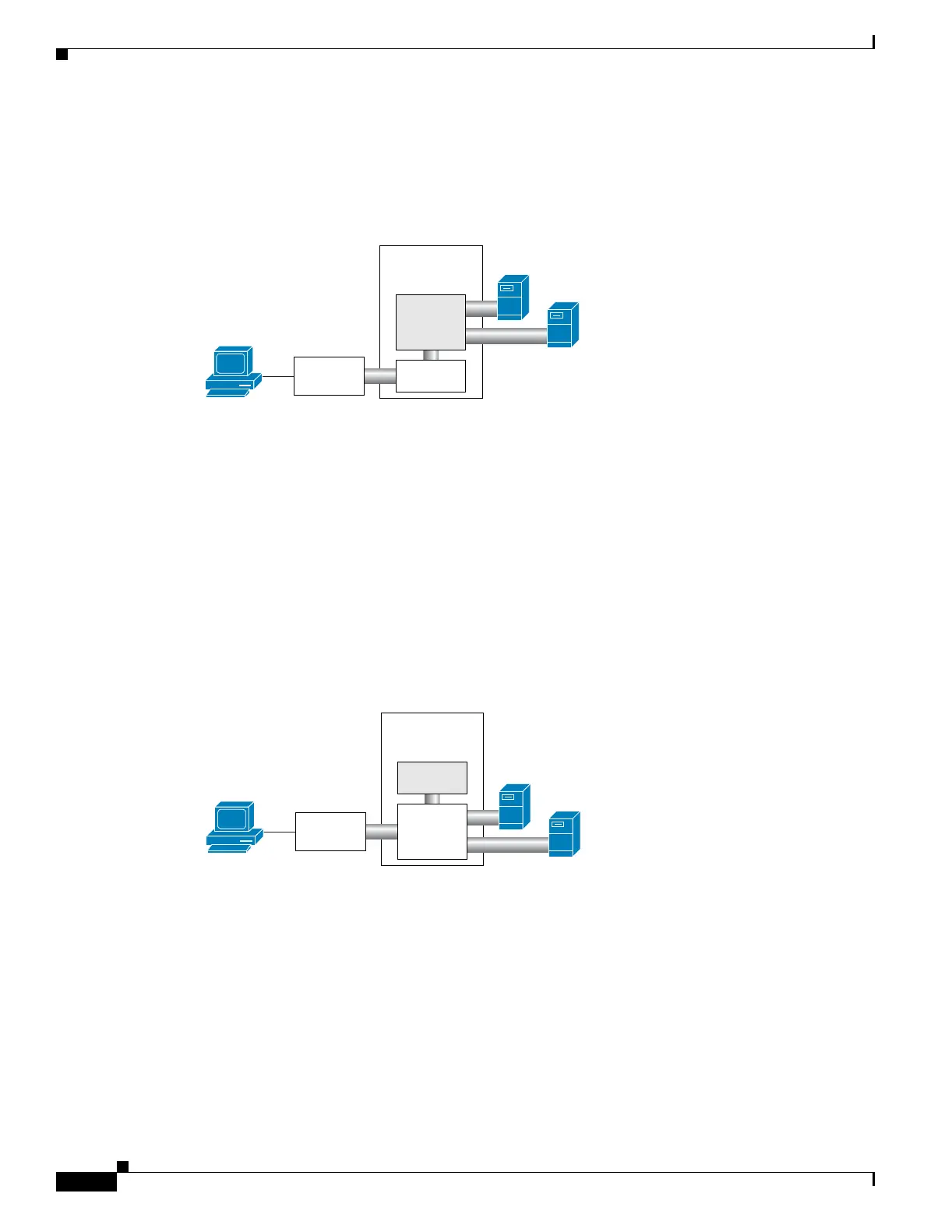
CSM Inline, MSFC on Client Side
Figure 2-4 shows the CSM in a configuration where the MSFC is located on the client side.
Figure 2-4 CSM Inline, MSFC Located on the Client Side
This configuration has these characteristics:
• The configuration is easy to deploy.
• Server-to-server Layer 3 communications pass through the CSM.
• Routing protocols can be used between the MSFC and the upstream router.
• All traffic to or from the servers passes through the CSM.
CSM in Aggregate Mode
Figure 2-5 shows the CSM in an aggregate-mode configuration.
Figure 2-5 CSM Located in Aggregate Mode
This configuration has these characteristics:
• The CSM is not inline and the module does not see unnecessary traffic.
• Easy routing and CSM configuration.
• Requires PBR or client SNAT because return traffic is required.
• Server-to-server load-balanced connections always require SNAT.
• Layer 2-rewrite is not possible.
Catalyst
6500
98156
CSM
MSFC
Upstream
router
Client
Servers
MSFC
Catalyst
6500
98158
Upstream
router
CSM
Client
Servers
 Loading...


