2-5
Catalyst 6500 Series Content Switching Module Configuration Note
OL-4612-01
Chapter 2 Networking with the Content Switching Module
CSM Networking Topologies
• CSM Inline, MSFC on Client Side, page 2-6
• CSM in Aggregate Mode, page 2-6
• Direct Server Return, page 2-7
CSM Inline, MSFC Not Involved
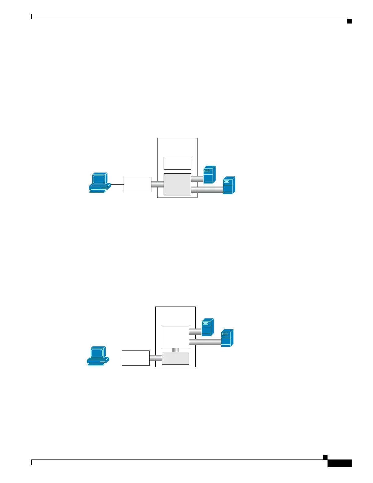
Figure 2-2 shows the CSM in a Layer 3 configuration without interaction with the MSFC.
Figure 2-2 CSM Inline, MSFC Not Involved
This configuration has these characteristics:
• The MSFC is not routing CSM VLANs.
• All server-to-server communications (direct Layer 3 or load balanced) are through the CSM.
• The CSM must use static routes to the upstream router (default gateway).
CSM Inline, MSFC on Server Side
Figure 2-3 shows the CSM in a configuration where the MSFC is located on the server side.
Figure 2-3 CSM Inline, MSFC Located on Server Side
This configuration has these characteristics:
• Server-to-server direct communications bypass the CSM.
• Server-to-server load-balanced connections always require secure NAT (SNAT).
• The CSM must use static routes to the upstream router (default gateway).
• Routing protocols can be used in the back end.
• Layer 2-rewrite is not possible.
CSM
MSFC
Catalyst
6500
98154
Upstream
router
Client
Servers
Catalyst
6500
98155
MSFC
CSM
Upstream
router
Servers
Client
 Loading...


