7-6
Catalyst 6500 Series Content Switching Module Configuration Note
OL-4612-01
Chapter 7 Configuring Redundant Connections
Configuring HSRP
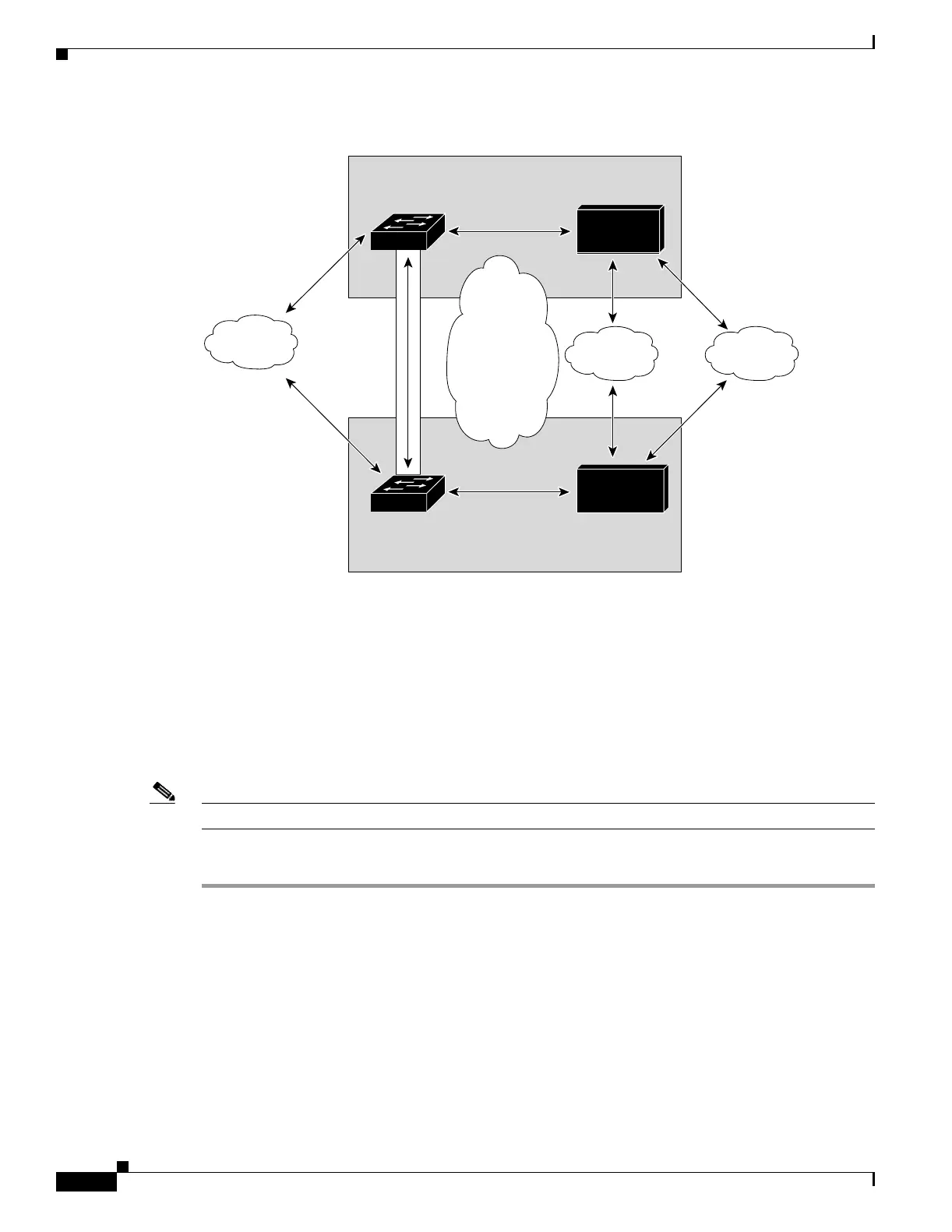
Figure 7-2 HSRP Configuration
Creating the HSRP Gateway
This procedure describes how to create an HSRP gateway for the client-side network. The gateway is
HSRP ID 2 for the client-side network.
Note In this example, HSRP is set on Fast Ethernet ports 3/6.
To create an HSRP gateway, follow these steps:
Step 1 Configure Switch 1—FT1 (HSRP active) as follows:
Router(config)# interface FastEthernet3/6
Router(config)# ip address 10.100.0.2 255.255.0.0
Router(config)# standby 2 priority 110 preempt
Router(config)# standby 2 ip 10.100.0.1
Client
Network
10.100/16
HSRP ID 2
(Gateway = 10.100.0.1)
VLAN 136, - Client Net
HSRP ID 1
(Gateway = 10.6.0.1)
With tracking ON
VLAN 272, - Server Net
(Gateway = 10.5.0.1) via
Secure Subnet and IP Alias
EtherChannel
ID=100 (Trunk)
VLAN 136
Allowed
10.100.0.2
10.6.0.2
10.5.0.2
10.5.0.3
10.6.0.3
10.100.0.3
Switch 2
Name: "FT2"
HSRP Secondary
CSM#2
FT Secondary
VLAN 71
FT Network
Server
Network
10.5/16
Switch 1
Name: "FT1"
HSRP Primary
120180
Internal
CSM
Client
Network
10.6/16
CSM#1
FT Primary
 Loading...


