2-3
Catalyst 6500 Series Content Switching Module Configuration Note
OL-4612-01
Chapter 2 Networking with the Content Switching Module
Configuring Modes for Networking
Note Set the server’s default routes to Router A’s gateway (192.158.38.20) or Router B’s gateway
(192.158.38.21).
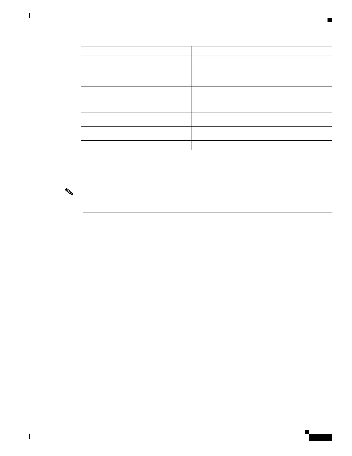
Step 9
Router(config-slb-vserver)# vlan 3
server
Creates the server-side VLAN 3 and enters the SLB
VLAN mode.
Step 10
Router(config-slb-vlan-client)# ip
addr 192.158.38.10 255.255.255.0
Assigns the CSM IP address on VLAN 3.
Step 11
Router(config-slb-vlan-client)# exit
Exits the submode.
Step 12
Router(config-module-csm)# vserver
VIP1
Creates a virtual server and enters the SLB virtual server
mode.
Step 13
Router(config-slb-vserver)# virtual
192.158.38.30 tcp www
Creates a virtual IP address.
Step 14
Router(config-slb-vserver)# serverfarm
farm1
Associates the virtual server with the server farm
3
.
Step 15
Router(config-module-csm)# inservice
Enables the server.
1. Enter the exit command to leave a mode or submode. Enter the end command to return to the menu’s top level.
2. The no form of this command restores the defaults.
3. This step assumes that the server farm has already been configured. (See the “Configuring Server Farms” section on
page 5-1.)
Command Purpose
 Loading...


