2-4
Catalyst 6500 Series Content Switching Module Configuration Note
OL-4612-01
Chapter 2 Networking with the Content Switching Module
CSM Networking Topologies
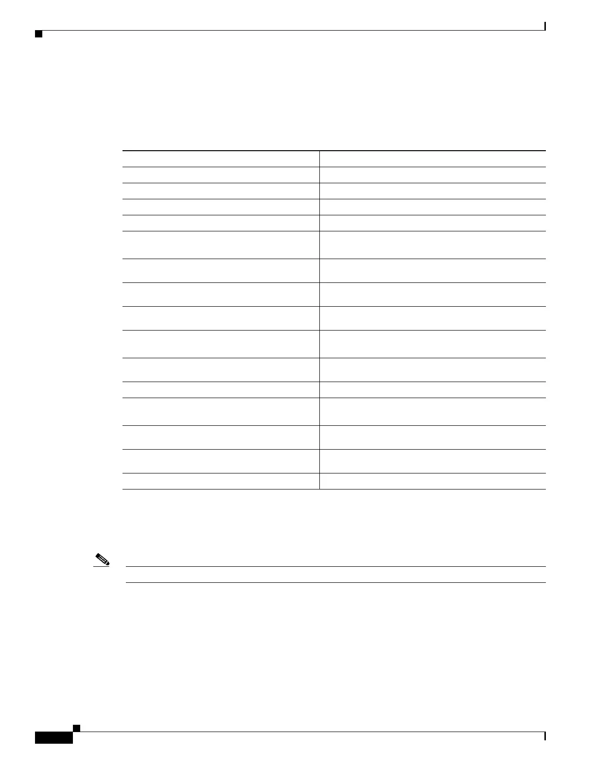
Configuring the Secure (Router) Mode
In secure (router) mode, the client-side and server-side VLANs are on different subnets.
To configure content switching in secure (router) mode, perform this task:
Note Set the server’s default routes to the CSM’s IP address (192.158.39.10).
CSM Networking Topologies
This section describes CSM networking topologies and contains these sections:
• CSM Inline, MSFC Not Involved, page 2-5
• CSM Inline, MSFC on Server Side, page 2-5
Command Purpose
Step 1
Router(config-module-csm)# vlan database
Enters the VLAN mode
1
.
1. Enter the exit command to leave a mode or submode. Enter the end command to return to the menu’s top level.
Step 2
Router(vlan)# vlan 2
Configures a client-side VLAN
2
.
2. The no form of this command restores the defaults.
Step 3
Router(vlan)# vlan 3
Configures a server-side VLAN.
Step 4
Router(vlan)# exit
Exits the mode for the configuration to take effect.
Step 5
Router(config-module-csm)# vlan 2 client
Creates the client-side VLAN 2 and enters the SLB
VLAN mode.
Step 6
Router(config-slb-vlan-client)# ip addr
192.158.38.10 255.255.255.0
Assigns the CSM IP address on VLAN 2.
Step 7
Router(config-slb-vlan-client)# gateway
192.158.38.20
Defines the client-side VLAN gateway to Router A.
Step 8
Router(config-slb-vlan-client)# gateway
192.158.38.21
Defines the client-side VLAN gateway to Router B.
Step 9
Router(config-module-csm)# vlan 3 server
Creates the server-side VLAN 3 and enters the SLB
VLAN mode.
Step 10
Router(config-slb-vlan-server)# ip addr
192.158.39.10 255.255.255.0
Assigns the CSM IP address on VLAN 3.
Step 11
Router(config-slb-vlan-server)# exit
Exits the submode.
Step 12
Router(config-module-csm)# vserver VIP1
Creates a virtual server and enters the SLB virtual
server mode.
Step 13
Router(config-slb-vserver)# virtual
192.158.38.30 tcp www
Creates a virtual IP address.
Step 14
Router(config-slb-vserver)# serverfarm
farm1
Associates the virtual server with the server farm
3
.
3. This step assumes that the server farm has already been configured. (See the “Configuring Server Farms” section on
page 5-1.)
Step 15
Router(config-module-csm)# inservice
Enables the server.
 Loading...


