2-2
Catalyst 6500 Series Content Switching Module Configuration Note
OL-4612-01
Chapter 2 Networking with the Content Switching Module
Configuring Modes for Networking
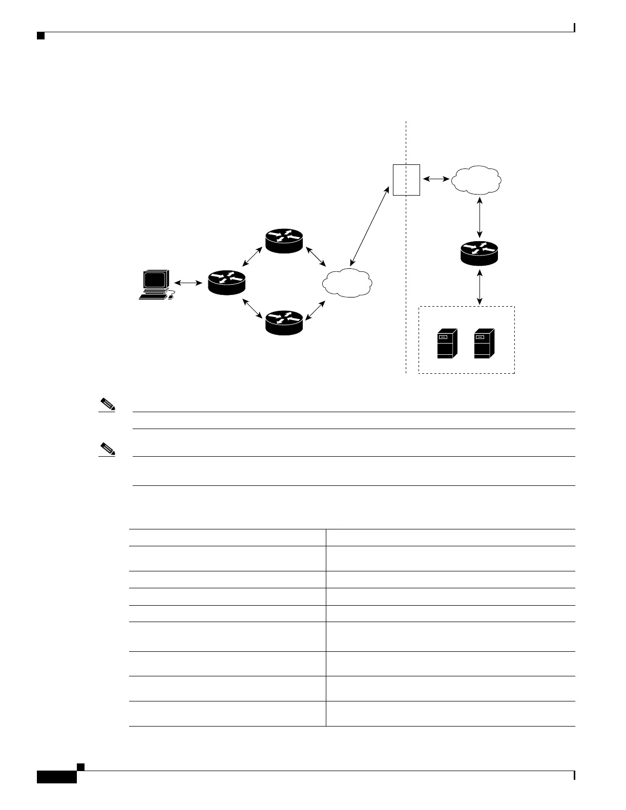
Figure 2-1 Single Subnet (Bridge) Mode Configuration
Note The addresses in Figure 2-1 refer to the steps in the following task table.
Note You configure single subnet (bridge) mode by assigning the same IP address to the CSM client and server
VLANs.
To configure content switching for the single subnet (bridge) mode, perform this task:
VLAN 2
Router A
NAS
router
Client
workstation
Router B
Client-side Server-side
Gateway
192.158.38.20
Gateway
192.158.38.21
192.158.38.10 192.158.39.10
VLAN 3
Virtual server 1
192.158.38.30
99427
Server A
Server Farm 1
Server B
Content provider
Content Switching Module
Command Purpose
Step 1
Router(config-module-csm)# vlan
database
Enters the VLAN mode
1
.
Step 2
Router(vlan)# vlan 2
Configures a client-side VLAN
2
.
Step 3
Router(vlan)# vlan 3
Configures a server-side VLAN.
Step 4
Router(vlan)# exit
Exits the mode for the configuration to take effect.
Step 5
Router(config-module-csm)# vlan 2
client
Creates the client-side VLAN 2 and enters the SLB
VLAN mode
1
.
Step 6
Router(config-slb-vlan-client)# ip
addr 192.158.38.10 255.255.255.0
Assigns the CSM IP address on VLAN 2.
Step 7
Router(config-slb-vlan-client)#
gateway 192.158.38.20
Defines the client-side VLAN gateway to Router A.
Step 8
Router(config-slb-vlan-client)#
gateway 192.158.38.21
Defines the client-side VLAN gateway to Router B.
 Loading...


