11-19
Catalyst 6500 Series Content Switching Module Configuration Note
OL-4612-01
Chapter 11 Configuring Firewall Load Balancing
Configuring Regular Firewall Load Balancing
Configuring Server Farms on CSM A
Note Firewall 1 and Firewall 2 secure-side IP addresses are configured as real servers in the SEC-SF
server farm associated with CSM B.
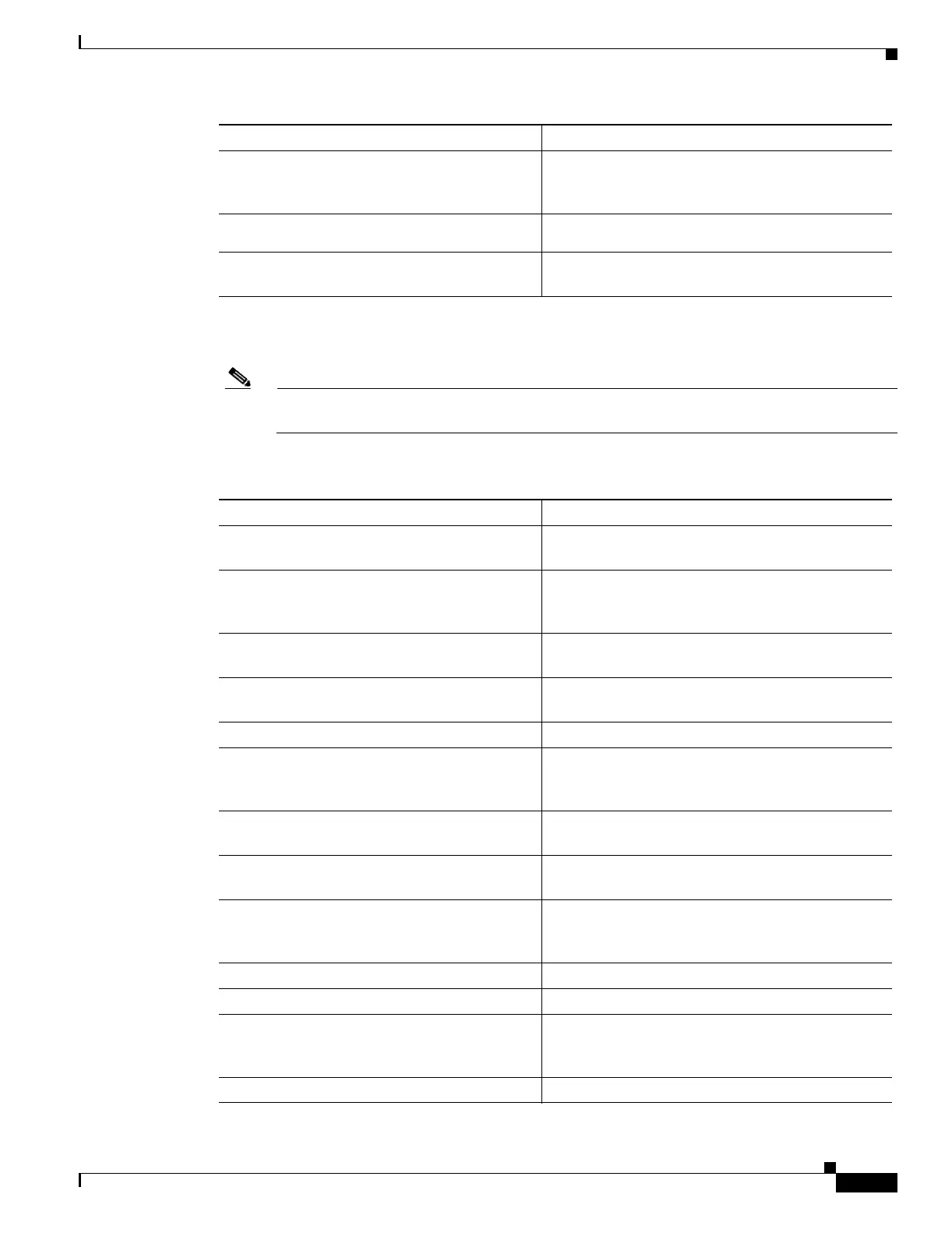
To configure two server farms on CSM A, perform this task:
Step 6
Switch-A(config-module-csm)# vlan 101
server
Specifies VLAN 101 as the VLAN that is being
configured, identifies it as a server VLAN, and
enters VLAN configuration mode.
Step 7
Switch-A(config-slb-vlan-server)# ip
address 100.0.0.25 255.255.255.0
Specifies an IP address and netmask for VLAN 101.
Step 8
Switch-A(config-slb-vlan-server)# alias
100.0.0.20 255.255.255.0
Specifies an alias IP address and netmask for VLAN
101
1
.
1. This step provides a target for CSM B to use in making a load-balancing decision.
Command Purpose
Command Purpose
Step 1
Switch-A(config)# module csm 5
Enters multiple module configuration mode and
specifies that CSM A is installed in slot 5.
Step 2
Switch-A(config-module-csm)# serverfarm
FORWARD-SF
Creates and names the FORWARD-SF
1
server farm
(actually a forwarding policy) and enters server farm
configuration mode.
Step 3
Switch-A(config-slb-sfarm)# no nat server
Disables the NAT of server IP addresses and port
numbers
2
.
Step 4
Switch-A(config-slb-sfarm)# predictor
forward
Forwards traffic by adhering to its internal routing
tables rather than a load-balancing algorithm.
Step 5
Switch-A(config-slb-sfarm)# exit
Returns to multiple module configuration mode.
Step 6
Switch-A(config-module-csm)# serverfarm
INSEC-SF
Creates and names the INSEC-SF
3
server farm
(which will contain firewalls as real servers) and
enters server farm configuration mode.
Step 7
Switch-A(config-slb-sfarm)# no nat server
Disables the NAT of the server IP address and port
number
4
.
Step 8
Switch-A(config-slb-sfarm)# predictor
hash address source 255.255.255.255
Selects a server using a hash value based on the
source IP address
5
.
Step 9
Switch-A(config-slb-sfarm)# real
100.0.0.3
Identifies Firewall 1 as a real server, assigns an IP
address to its insecure side, and enters real server
configuration submode.
Step 10
Switch-A(config-slb-real)# inservice
Enables the firewall.
Step 11
Switch-A(config-slb-real)# exit
Returns to server farm configuration mode.
Step 12
Switch-A(config-slb-sfarm)# real
100.0.0.4
Identifies Firewall 2 as a real server, assigns an IP
address to its insecure side, and enters real server
configuration submode.
Step 13
Switch-A(config-slb-real)# inservice
Enables the firewall.
 Loading...


