To provide N+1 protection, the following number of power supplies is recommended:
•
Three power supplies are recommended if the power configuration for that chassis requires greater than
2500 W or if using UCS Release 1.4(1) and later releases
•
Two power supplies are sufficient if the power configuration for that chassis requires less than 2500 W
or the system is using UCS Release 1.3(1) or earlier releases
•
Four power supplies are recommended when running the dual-voltage power supply from a 100 - 120V
source.
Adding an additional power supply to either of these configurations will provide an extra level of protection.
Cisco UCS Manager turns on the extra power supply in the event of a failure and restores N+1 protection.
An n+1 redundant system has either two or three power supplies, which may be in any slot.Note
Grid Redundancy
The grid redundant configuration is sometimes used when you have two power sources to power a chassis or
you require greater than N+1 redundancy. If one source fails (which causes a loss of power to one or two
power supplies), the surviving power supplies on the other power circuit continue to provide power to the
chassis. A common reason for using grid redundancy is if the rack power distribution is such that power is
provided by two PDUs and you want the grid redundancy protection in the case of a PDU failure.
To provide grid redundant (or greater than N+1) protection, the following number of power supplies is
recommended:
•
Four power supplies are recommended if the power configuration for that chassis requires greater than
2500W or if using Cisco UCS Release 1.4(1) and later releases
•
Two power supplies are recommended if the power configuration for that chassis requires less than
2500W or the system is using Cisco UCS Release 1.3(1) or earlier releases
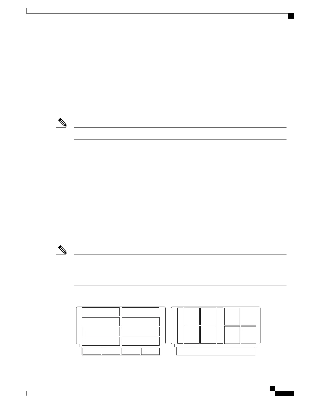
Both grids in a power redundant system should have the same number of power supplies. If your system
is configured for grid redundancy, slots 1 and 2 are assigned to grid 1 and slots 3 and 4 are assigned to
grid 2. If there are only two power supplies (PS) in the a redundant mode chassis, they should be in slots
1 and 3. Slot and cord connection numbering is shown below.
Note
Figure 17: Power Supply Bay and Connector Numbering
PS 1
PS 2
PS 3
PS 4
Server Slot 1
Server Slot 2
Server Slot 3
Server Slot 5
Server Slot 7
Server Slot 4
Server Slot 6
Server Slot 8
Front
Fan 1
Fan 2
I/O Module Slot 1
I/O Module Slot 2
Connector
PS 4
Connector
PS 3
Connector
PS 2
Connector
PS 1
Fan 6
Fan 5
Fan 4
Fan 3
Fan 8
Fan 7
Rear
279770
Cisco UCS 5108 Server Chassis Installation Guide
33
Overview
Power Supplies

 Loading...


