Installing a Power Supply
All power supply models (N20-PAC5-2500W, UCSB-PSU-2500ACPL, or UCSB-PSU-2500DC48) install
using the same process.
Procedure
Step 1
Place the power supply’s handle in the up position.
Step 2
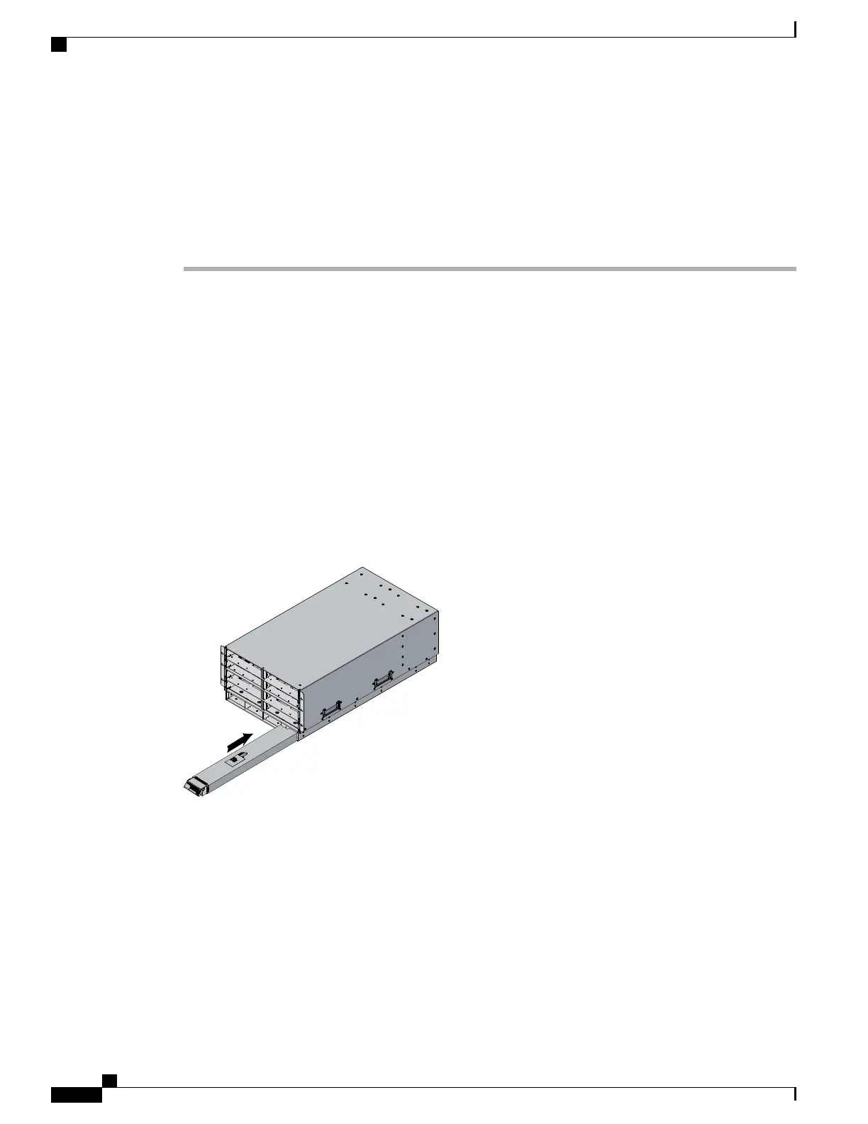
Hold the power supply with both hands, and then slide it into the power supply bay,
Step 3
Press the handle down, and give the power supply a gentle push inward to ensure that the power supply is
fully seated into the Power Distribution Unit (PDU).
Step 4
Tighten the captive screw.
Step 5
For an AC installation, plug the power cable into the corresponding 220 VAC–inlet connector on the PDU at
the rear of the chassis. For a DC environment, see Connecting a DC Power Supply, on page 55.
Depending on the outlet receptacle on your rack’s power distribution unit, you may need the optional
jumper power cord to connect the Cisco UCS 5108 server chassis to an outlet receptacle.
Note
Step 6
Connect the other end of the power cable to the AC–power source.
Step 7
Verify the power supply is operating by checking the power supply LEDs. See LED Locations, on page 35
and Interpreting LEDs, on page 36.
Figure 45: Positioning a Power Supply in the Cisco UCS Server Chassis
Both grids in a power redundant system should have the same number of power supplies. If your
system is configured for grid redundancy, slots 1 and 2 are assigned to grid 1 and slots 3 and 4 are
assigned to grid 2. If there are only two power supplies in a redundant- mode chassis, they should
be in slots 1 and 3. This would be a very unusual configuration, with a single B200 blade server in
the chassis. A larger configuration would require two power supplies per grid. Slot and cord connection
numbering is shown below.
Note
Cisco UCS 5108 Server Chassis Installation Guide
74
Installing and Removing Components
Installing a Power Supply

 Loading...


