EasyManuals Logo

Cisco UCS 5108 Installation Guide

Cisco UCS 5108
114 pages
To Next Page IconTo Next Page
To Previous Page IconTo Previous Page
Page #82 background imageLoading...
Page #82 background image
Whenever you remove a module from the chassis for an extended period of time, always replace the
module with the appropriate blank panel. Failing to do so can result in heating and EMI issues. Blank
panels can be ordered from Cisco Systems.
Note
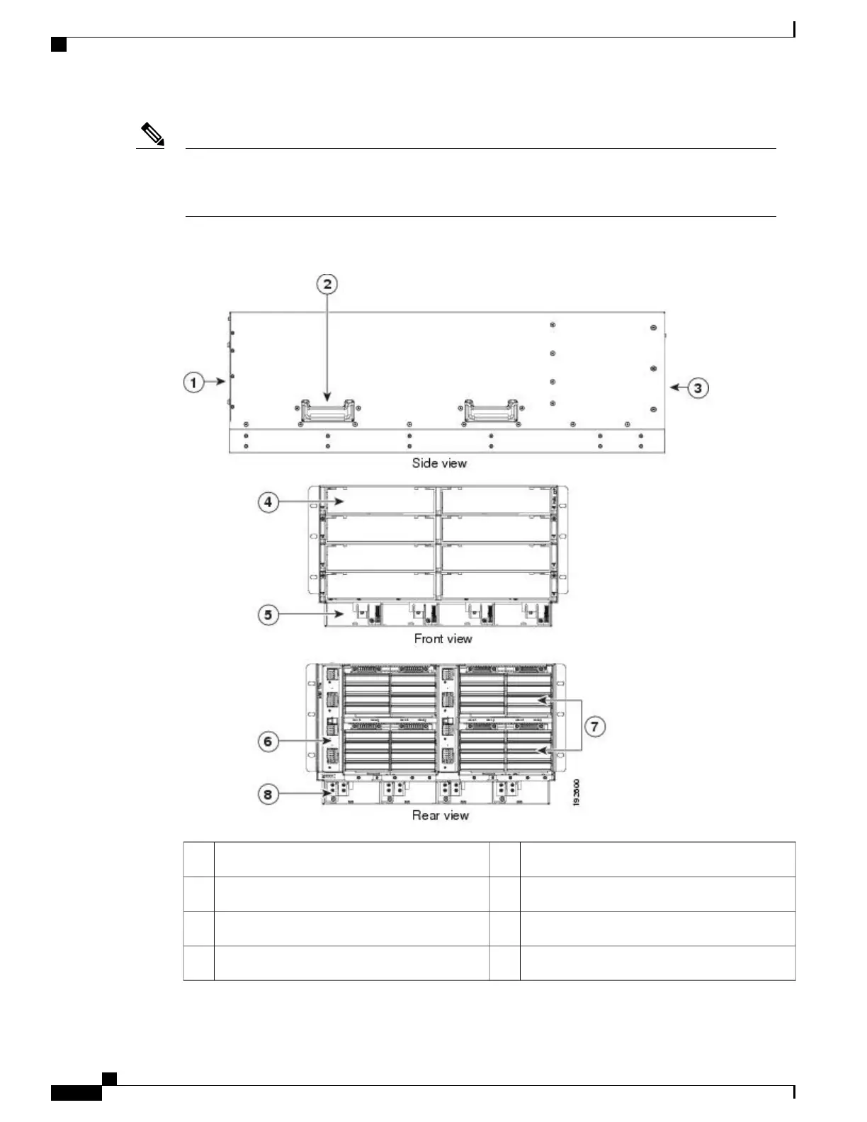
Figure 42: View of Cisco UCS 5108 Server Chassis
Power supply slot (4 slots)5Front of chassis1
Fabric interconnect or FEX slot (2 slots)6Chassis handle2
Fan slots (8 slots)7Rear of chassis3
Power Distribution Unit (PDU) slot8Half-width server slot (8 slots)4
Cisco UCS 5108 Server Chassis Installation Guide
70
Installing and Removing Components
Components

Table of Contents

Other manuals for Cisco UCS 5108

Questions and Answers:

Question and Answer IconNeed help?

Do you have a question about the Cisco UCS 5108 and is the answer not in the manual?

Cisco UCS 5108 Specifications

General IconGeneral
Number of Blade Slots8
I/O Module Bays2
Supported Blade ServersCisco UCS B-Series Blade Servers
Power Supply OptionsUp to four hot-swappable power supplies (AC or DC)
CoolingRedundant hot-swappable fans
ManagementCisco UCS Manager
Blade Slots8
Fabric InterconnectsCisco UCS 6100 or 6200 Series
Power SuppliesUp to 4 hot-pluggable power supplies
Form Factor6RU rack-mountable

Related product manuals