EasyManuals Logo

Cisco UCS 5108 Installation Guide

Cisco UCS 5108
114 pages
To Next Page IconTo Next Page
To Previous Page IconTo Previous Page
Page #67 background imageLoading...
Page #67 background image
Procedure
Step 1
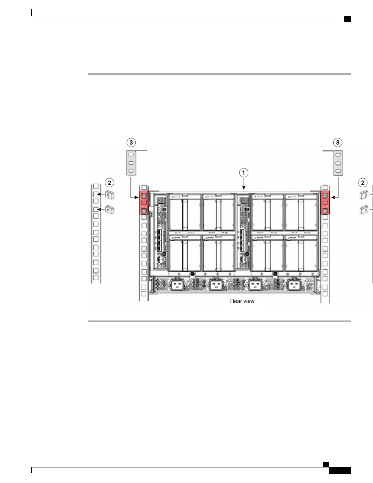
Install the UCS 5108 or UCS Mini chassis. See callout 1 in the following figure.
Step 2
Attach the supplied cage nuts to the rack rails for the left and right brackets. See callout 2. The tightening
torque is 45 lb-in (5.0 N-m).
Step 3
Secure the brackets using the supplied screws. See callout 3.
Figure 34: Installing the Rear Brackets to the Chassis
Connecting a DC Power Supply
This section describes how to connect power to the rear PDU terminals on the DC version chassis
(UCSB-5108-DC) corresponding to a UCS 5108 DC power supply (UCSB-PSU-2500DC48).
Required Tools
You must have the following tools to perform this procedure:
A Phillips screwdriver
Cisco UCS 5108 Server Chassis Installation Guide
55
Installation
Connecting a DC Power Supply

Table of Contents

Other manuals for Cisco UCS 5108

Questions and Answers:

Question and Answer IconNeed help?

Do you have a question about the Cisco UCS 5108 and is the answer not in the manual?

Cisco UCS 5108 Specifications

General IconGeneral
Number of Blade Slots8
I/O Module Bays2
Supported Blade ServersCisco UCS B-Series Blade Servers
Power Supply OptionsUp to four hot-swappable power supplies (AC or DC)
CoolingRedundant hot-swappable fans
ManagementCisco UCS Manager
Blade Slots8
Fabric InterconnectsCisco UCS 6100 or 6200 Series
Power SuppliesUp to 4 hot-pluggable power supplies
Form Factor6RU rack-mountable

Related product manuals