EasyManuals Logo

Cisco UCS 5108 Installation Guide

Cisco UCS 5108
114 pages
To Next Page IconTo Next Page
To Previous Page IconTo Previous Page
Page #88 background imageLoading...
Page #88 background image
Installing a PDU
Procedure
Step 1
Hold the PDU module from below, with the captive screws at the top of the module.
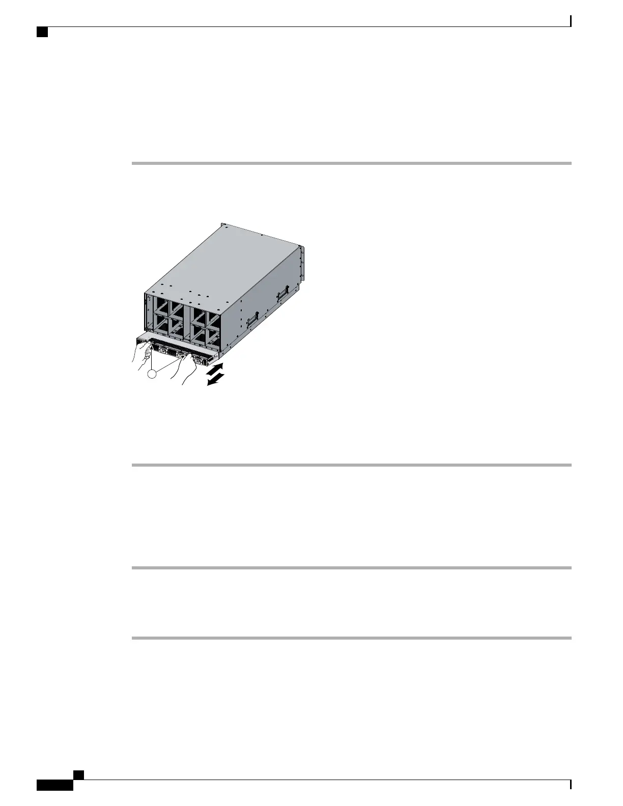
Figure 47: Positioning a PDU (N01-UAC1) in the Cisco UCS Server Chassis, AC Version
195360
1
Step 2
Push the PDU module into the chassis until it seats properly. If power supplies are installed, you may need
to partially remove them.
Step 3
Tighten the captive screws.
Step 4
If necessary, reseat the power supplies and restart the system to observe LED behavior.
Removing a PDU
Procedure
Step 1
Partially remove all installed power supplies. If a power supply is seated into the PDU, removal is difficult
or impossible.
Step 2
Loosen the captive screws.
Step 3
Pull the PDU clear of the chassis by pulling on the captive screws. Support its weight from below.
Cisco UCS 5108 Server Chassis Installation Guide
76
Installing and Removing Components
Installing a PDU

Table of Contents

Other manuals for Cisco UCS 5108

Questions and Answers:

Question and Answer IconNeed help?

Do you have a question about the Cisco UCS 5108 and is the answer not in the manual?

Cisco UCS 5108 Specifications

General IconGeneral
Number of Blade Slots8
I/O Module Bays2
Supported Blade ServersCisco UCS B-Series Blade Servers
Power Supply OptionsUp to four hot-swappable power supplies (AC or DC)
CoolingRedundant hot-swappable fans
ManagementCisco UCS Manager
Blade Slots8
Fabric InterconnectsCisco UCS 6100 or 6200 Series
Power SuppliesUp to 4 hot-pluggable power supplies
Form Factor6RU rack-mountable

Related product manuals