APPPENDIX A:
Voice and fax boards
117
Hardware settings
Do the following procedures as you install voice boards.
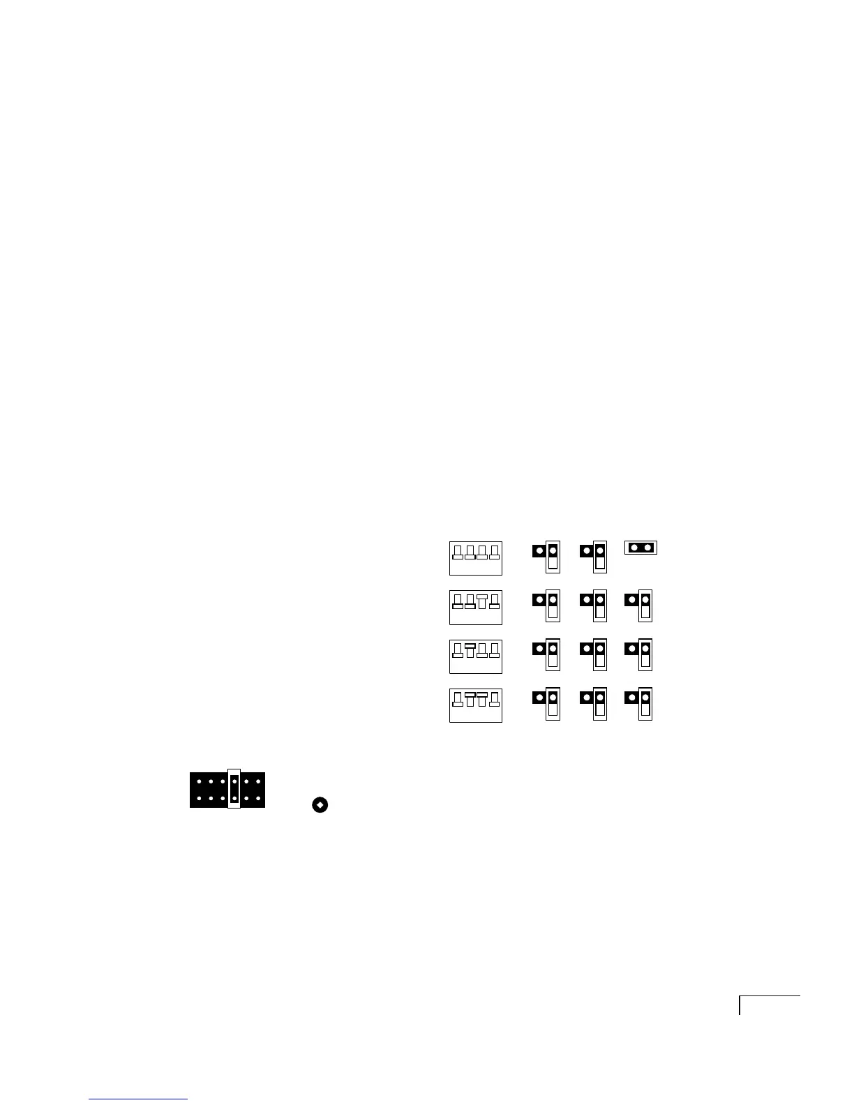
To set switch block SW1 and jumpers JP5, JP6,
and JP7
The switch block SW1 and jumper JP6 settings identify the voice
board’s memory address, which in turn specifies which voice
messaging ports are on which board. The jumper JP7 setting
specifies which board is in the first slot.
a Set SW1 switches on each board:
Turnkey system
Set SW1 switches as shown below.
Component system
Set SW1 switches to values that you
identified in the procedure “To find and reserve memory
addresses and an IRQ (ISA boards in a component system
only),” on page 35.
b Set jumpers JP5, JP6, and JP7 as shown below.
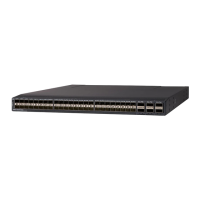
To set jumper JP1 (IRQ setting)
Set jumper JP1 on all boards to position 4, IRQ 5, as shown
in the diagram at left.
Continued
SW1 JP5 JP6 JP7
Memory
address
First board
Ports 1–4
D0000
Second board
Ports 5–8
D2000
Third board
Ports 9–12
D4000
Fourth board
Ports 13–16
D6000
On
Off
1234
On
Off
1234
On
Off
1234
On
Off
1234
JP1