Chapter 1 Overview
Rear-Panel Description
1-20
Catalyst 2950 Desktop Switch Hardware Installation Guide
78-11157-02
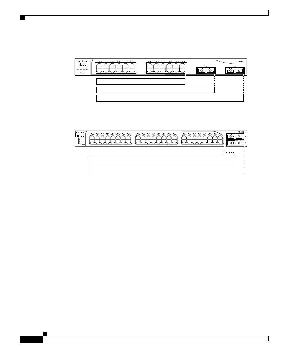
Figure 1-17 Bandwidth Utilization on Catalyst 2950G-24-EI and 2950G-24-EI-DC
Switches
Figure 1-18 Bandwidth Utilization on Catalyst 2950G-48-EI Switches
Rear-Panel Description
Other than the Catalyst 2950G-24-EI-DC switch, the rear panel of a Catalyst 2950
switch has an AC power connector, an RPS connector, and an RJ-45 console port.
(See Figure 1-19 and Figure 1-20.)
The rear panel of the Catalyst 2950G-24-EI-DC switch has a DC power connector
(also referred to as the terminal block header), a DC ground lug, an RPS
connector, and an RJ-45 console port. (See Figure 1-21.)
MODE
65396
2
Catalyst 2950
1
< 25% +
25% – 49% +
50% +
1
1X
2X
11X
12X
13X
14X
15X
16X
2 3 4 5 6 7 8 9 10 11 12 13 14 15 16 17 18 19 20 21 22 23 24
STAT
SYST RPS
UTIL DUPLX SPEED
65510
2
Catalyst 2950
1
< 25% +
1
1X
2X
15X
16X
2 3 24 5 6 7 8 9 10 11 12 13 14 15 16 17
17X
18X
31X
32X
18 19 20 21 22 23 24 25 26 27 28 29 31 31 32 33
33X
34X
47X
48X
34 35 36 37 38 39 40 41 42 43 44 45 46 47 48
50% +
25% – 49% +
SYST
RPS
STAT
UTIL
DUPLX
SPEED
MODE

 Loading...


