Chapter 1 Overview
Rear-Panel Description
1-22
Catalyst 2950 Desktop Switch Hardware Installation Guide
78-11157-02
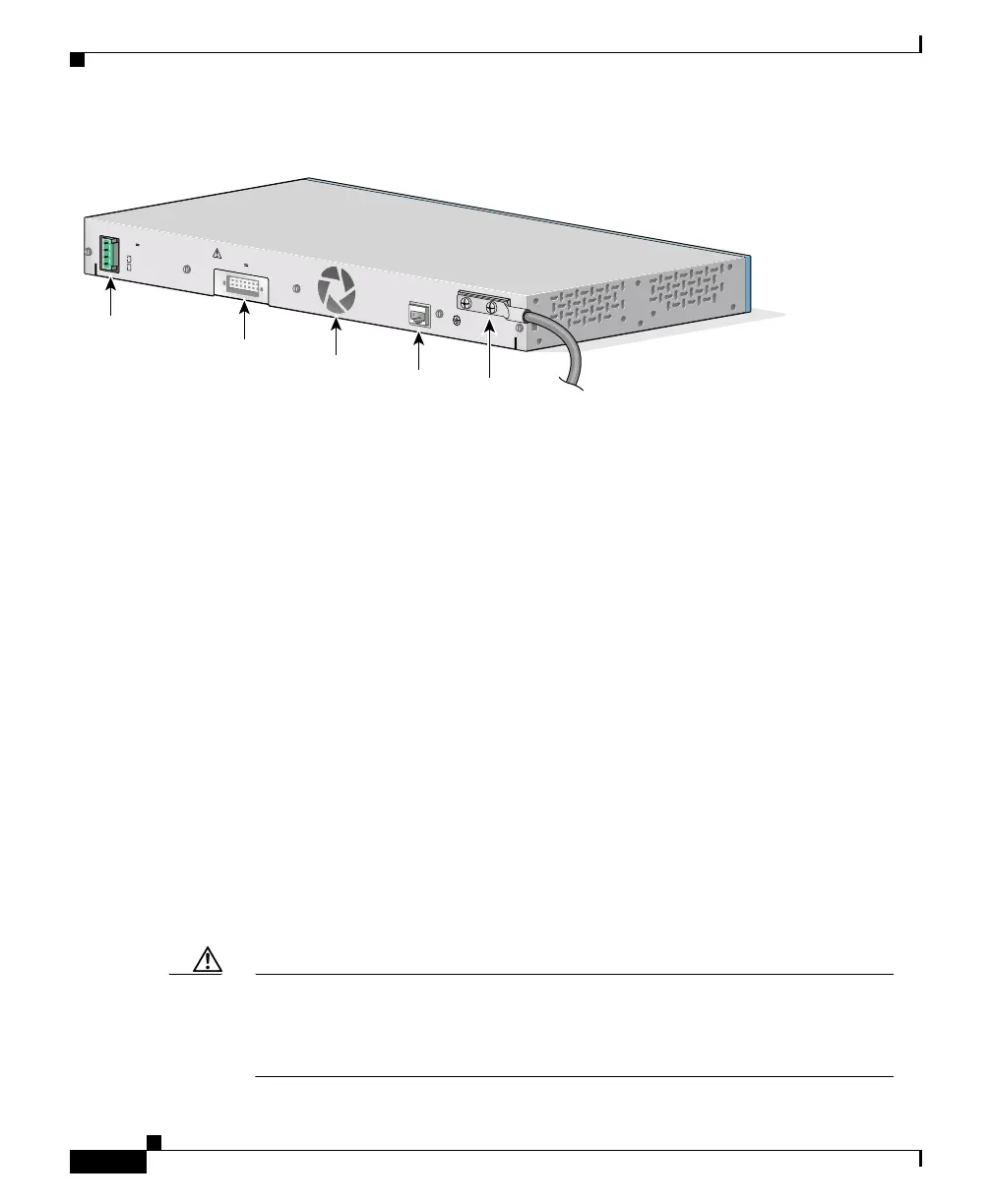
Figure 1-21 Catalyst 2950G-24-EI-DC Switch Rear Panel
Power Connectors
You can provide power to a switch by using the AC internal power supply, the
DC-input power source, or the Cisco RPS.
Internal Power Supply Connector
The internal AC power supply is an autoranging unit that supports input voltages
between 100 and 240 VAC. Other than for the Catalyst 2950G-24-EI-DC switch,
use the supplied AC power cord to connect the AC power connector to an AC
power outlet.
DC Power Connector
The Catalyst 2950G-24-EI-DC switch has an internal DC-power converter. It has
dual feeds (A and B) that are diode-OR-ed into a single power block. For
installation instructions, see the “Connecting to DC Power” section on page 2-20.
Caution You must connect the Catalyst 2950G-24-EI-DC switch only to a DC-input
power source that has an input supply voltage from –36 to –72 VDC. If the
supply voltage is not in this range, the switch might not operate properly or
might be damaged.
DC INPUT FOR REMOTE
POWER SUPPLY
SPECIFIED IN MANUAL.
+12V @4.5A
36 - 72V
1 - 0.5A
A
B
CONSOLE
DC power
connector
RPS
connector
Fan
RJ-45
console
port
DC
ground
lug
65291

 Loading...


