WS2H and WS3 Manual Page 51
M X F STAINLESS STEEL, 0.7 – 150 GPM
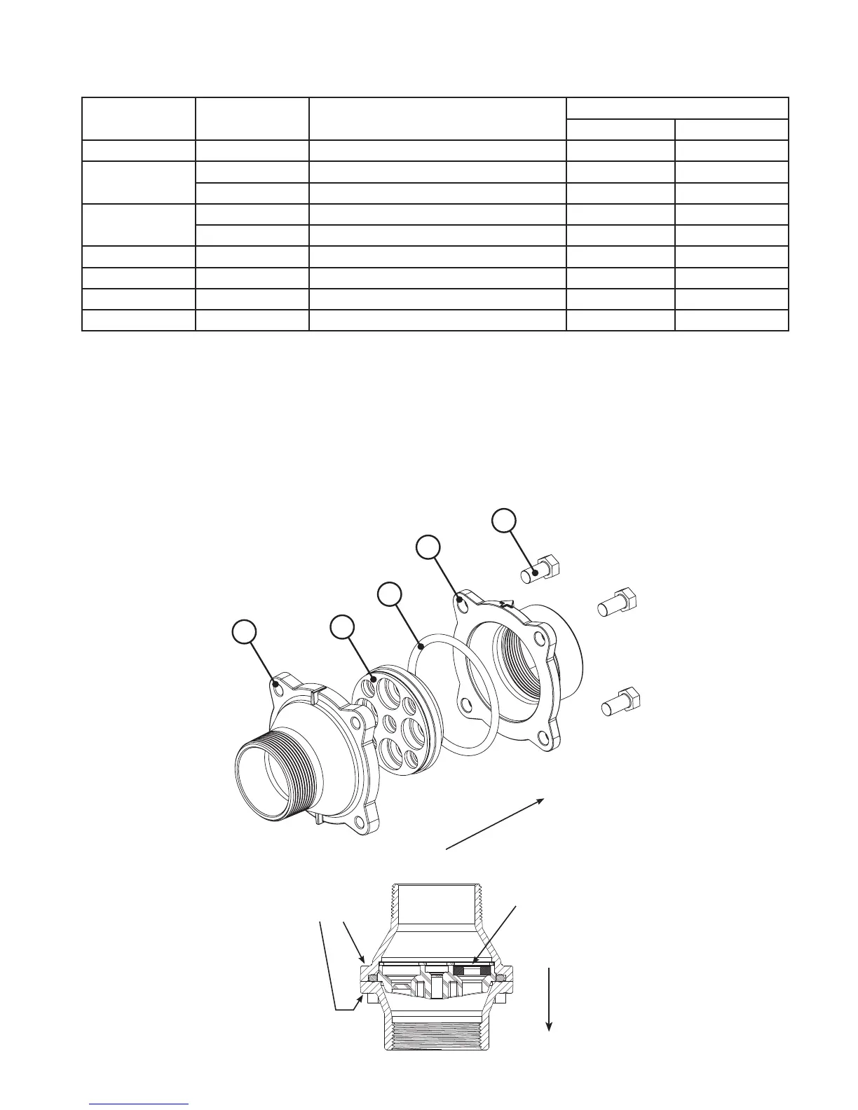
Assemblies are shipped without drain line ow control (DLFC). Assembly instructions:
1. Determine the desired owrate. Select a combination of V3162-XXX’s and V3190-XXX’s to arrive at the
desired ow rate. Up to ve of the smaller V3162-XXX’s may be used. Up to four of the larger V3190-XXX’s
may be used.
2. Using a drill or punch remove the desired knockout(s) in V3052.
3. Smooth hole(s).
4. Install appropriate size(s) of drain line ow control washers. Pay close attention to proper DLFC orientation.
5. Assemble. Properly orientate the V3052 in the direction of ow.
6. Inlet and outlet threads are 2”. Couplings for iron pipe may also be used.
1
2
5
3
4
Direction of Flow
B indictates BSPT
N indicates NPT
Washer
Radius
Direction
of Flow
Drawing
No.
Order
No.
Description
Quantity
V3051 V3051BSPT
1 V3052 WS2 DLFC Retainer Asy 1 1
2
V3245 WS2 DLFC Flange Inlet NPT 1
V3245BSPT WS2 DLFC Flange Inlet BSPT 1
3
V3246 WS2 DLFC Flange Outlet NPT 1
V3246BSPT WS2 DLFC Flange Outlet BSPT 1
4 V3273 Bolt Hex Hd S/S HCS 3/8-16x3/4 4 4
5 V3278 O-ring 338 1 1
6 V3162-XX See DLFC table 0-5 0-5
7 V3190-XX See DLFC table 0-4 0-4