WS2H and WS3 Manual Page 7
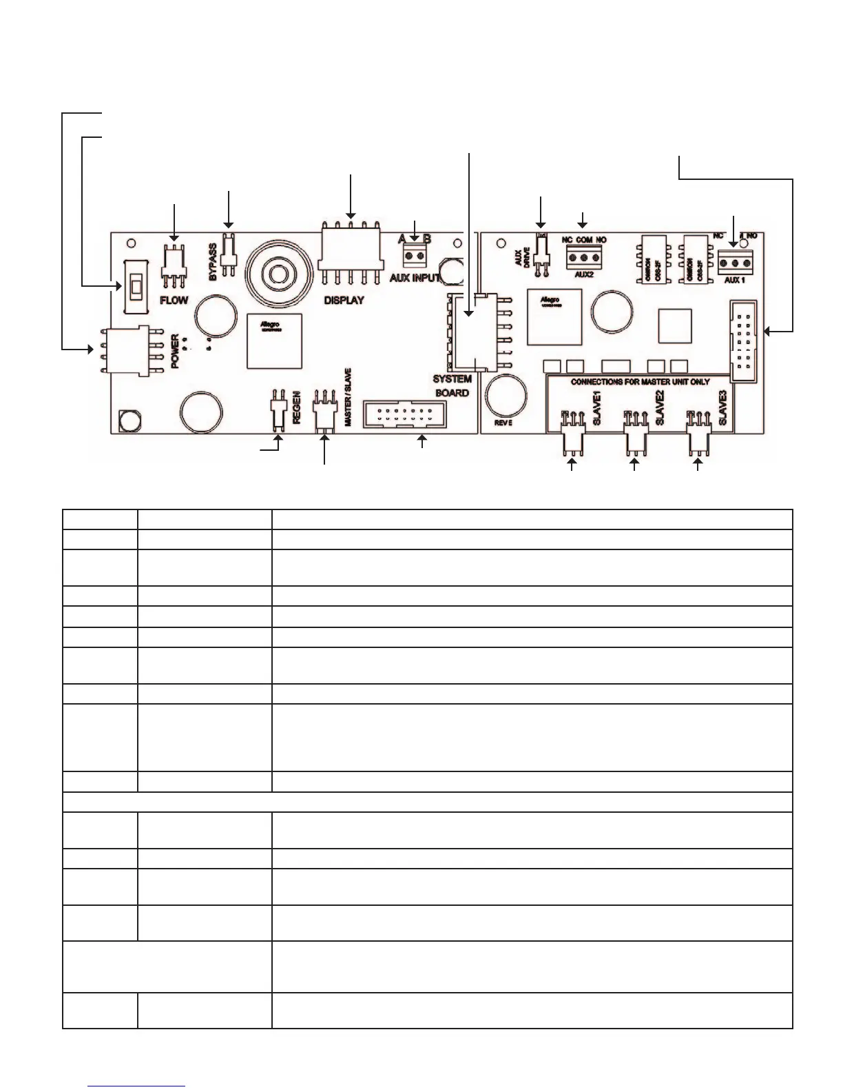
MAIN PC BOARD WITH SYSTEM BOARD
1) Power Supply
2) Manual Override Switch
3) Flow
Meter
4) Motorized
Alternating
Valve
5) POD
Display
Connection
6) Auxiliary
Input
10) System Board
Connection
9) Drive Motor
8) Communication Port
7) Programming
Port
11) Auxiliary
Drive
13) Relay 2 12 ) Relay 1
11) Programming
Port
14) Communication Ports
Item Board label Description
1 POWER Connect to proper power supply
2 SW1
Manual override switch used to force isolation (On Line or Standby status)
The units corresponding LED will ash twice / second to alert its override condition
3 FLOW Input for the units ow meter
4 BYPASS Drive circuit for factory motorized isolating valve (MAV or NoHBP)
5 DISPLAY Connection for POD display or data extraction with the proper software and cabling
6 AUX INPUT Connect to external dry contacts to control functionality based on the unit’s settings
**Wiring units inputs in parallel requires matching each units polarity**
7 PROGRAM Factory use only
8 MASTER/SLAVE Communication port on the main board can be used on the master of a 2 unit system &
is the communication port for any slave unit
**Greater than 2 unit systems require the optional system board on the master for
additional ports**
9 REGENERATION Motor circuit used to power the main drive of the unit during regeneration
The following connections are for an optional expansion board
10 SYSTEM BOARD
Connection for the optional V3243 system board to expand communication ports, add
a second motor circuit or relay output functionality
11 AUX DRIVE 2nd Drive circuit for factory motorized isolating valve (MAV or NoHBP)
12 AUX 1 Dry contact outputs to operate external devices based on the program settings of
Relay 1
13 AUX 2 Dry contact outputs to operate external devices based on the program settings of
Relay 2
Maximum power through either relay to be:
A) 1A, 30 VDC
B) 1A, 30 VAC
14 SLAVE 1, 2 or 3
Expanded communication ports for connecting up to 3 additional units to the master
unit in a system