WS2H and WS3 Manual Page 9
TYPICAL SYSTEM EXAMPLES (CONTINUED)
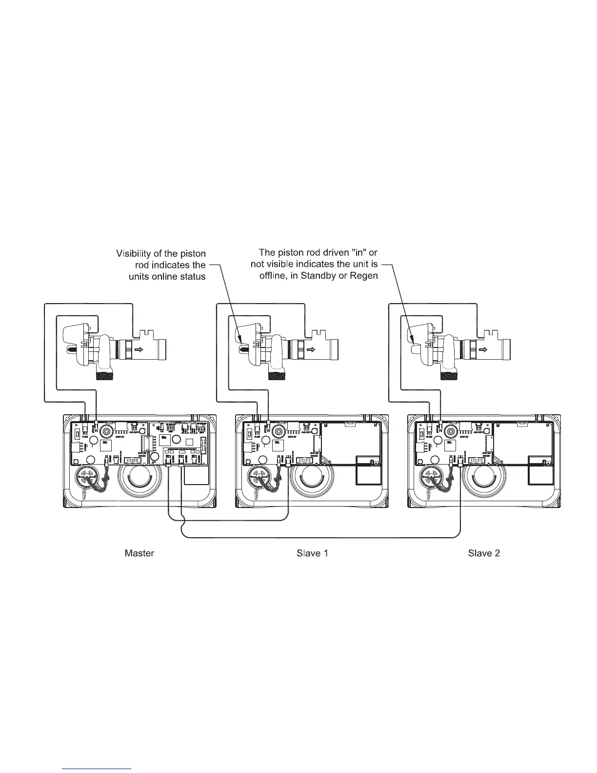
Multi-tank System, 3 Unit shown
System consists of 3 power heads, 2 communication cables and 3 No Hard Water Bypass (Isolation) valves
Electrical Connections:
• Each unit’s isolation valve motor wire is connected to the 2-pin connector labeled BYPASS on each unit’s PC board.•
The communication cable is connected to each unit’s 3-pin connector labeled MASTER/SLAVE
• Communication cables are connected to each unit’s 3-pin connector labeled MASTER/SLAVE. NOTE: Systems with
more than 2 units require the Master Unit to have the optional System Board for communication port expansion,
routing communications from the expansion ports (Slave 1, 2 or 3) to each unit’s MASTER/SLAVE connector.
Plumbing Connections:
• To regenerate with raw/treated water, the isolation valve is piped into the outlet of each unit.
• To regenerate with soft/treated water, the isolation valve is piped into the inlet of each unit.