Clear-Com®
Tempest®2400 2-Channel Wireless Intercom System 13
Power Connecons
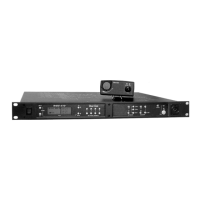
The Tempest BaseStaon can be powered from AC or DC power. The front panel ON/OFF switch controls AC and DC power
coming into the BaseStaon. If AC and DC are both connected, the DC will act as a power supply backup in the event AC
power is interrupted.
AC Power Connecon
» The Tempest BaseStaon can be powered from AC power sources.
» Always connect the power cord to the Tempest BaseStaon before connecng to the outlet.
» Only use approved IEC AC power cords.
» Only use AC power from 85 to 260 VAC at 50 – 60 Hz.
DC Power Connecon (Baery)
» To power the Tempest BaseStaon from DC power you must provide an appropriate DC power input cable.
» The DC power input jack on the BaseStaon is a Switchcra 722RA.
» The mang plug is a Switchcra S760 - 2.1mm x 5.5mm power plug. The connector should be wired as center
posive.
» Always use appropriate wire of an acceptable gauge and length for your applicaon. The minimum
recommended wire is 26 gauge at not more than ve feet. If 10 feet is required the minimum gauge would be 24.
» Only use DC power from 11 to 32 VDC. The Tempest BaseStaon will draw approximately 12 Was (990mA at
12VDC).
Powering On the BaseStaon
Turn the front panel ON/OFF switch to the ON posion.
The BaseStaon undergoes an inializaon cycle. During this power up cycle the LEDs ash and the LCD screen updates.
Approximately 4 seconds aer turning on the power switch you will see a splash screen showing the installed rmware
version. The splash screen last approximately 6 seconds before advancing to the normal Operaon screen. If connected to
a Local Area Network, the DHCP sengs (IP address, MAC address, etc) will then display unl MENU is pressed to escape
or unl the normal meout is completed. The system will then display the main Operaon screen and will be ready for
normal use.