Clear-Com®
Tempest®2400 2-Channel Wireless Intercom System 15
Antenna Conguraons
When aaching the supplied ½ Wave Omni-direconal Whip antenna directly to the back of the BaseStaon, always ensure
that the antenna are rmly seated, are not cross threaded, and are located away from any metal obstrucons. Keep the
antenna away from walls or other signicant structures by at least 24 inches.
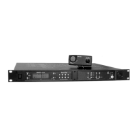
Opon 1
Install the BaseStaon in the center of the area
of communicaon, with antenna installed on
the back of the BaseStaon, having a clear
line of sight in all direcons.
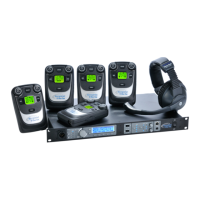
Opon 2
Install the BaseStaon in a convenient
locaon and use an oponal LMR-400, a 50
ohm coax cable up to 25 to connect an
oponal direconal antenna. (15 of LMR-
400 induces about 1 dB of aenuaon.) Note:
Direconal antennas are subject to legal
restricons in some countries.
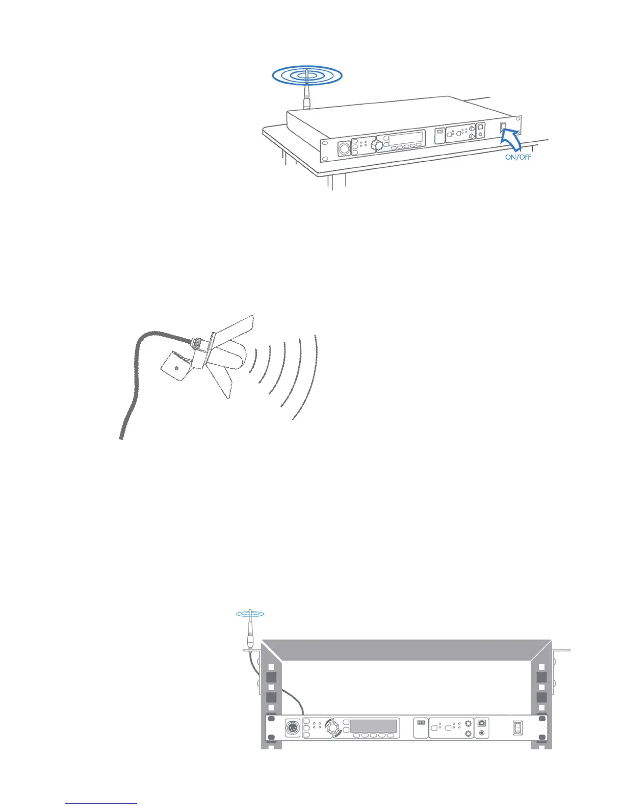
Opon 3
Install the BaseStaon in an equipment rack
(1 RU) and use an oponal LMR-195, a 50
ohm coax up to 10 to mount the antenna
above the equipment rack. (5 of LMR-195
coax induces about 1 dB of aenuaon.)