THE SMART SOLUTION FOR ENERGY EFFICIENCY
MPC MultiProtoCol DDC Controls
November 19, 2018
27
(Read Left to Right Across Spread)
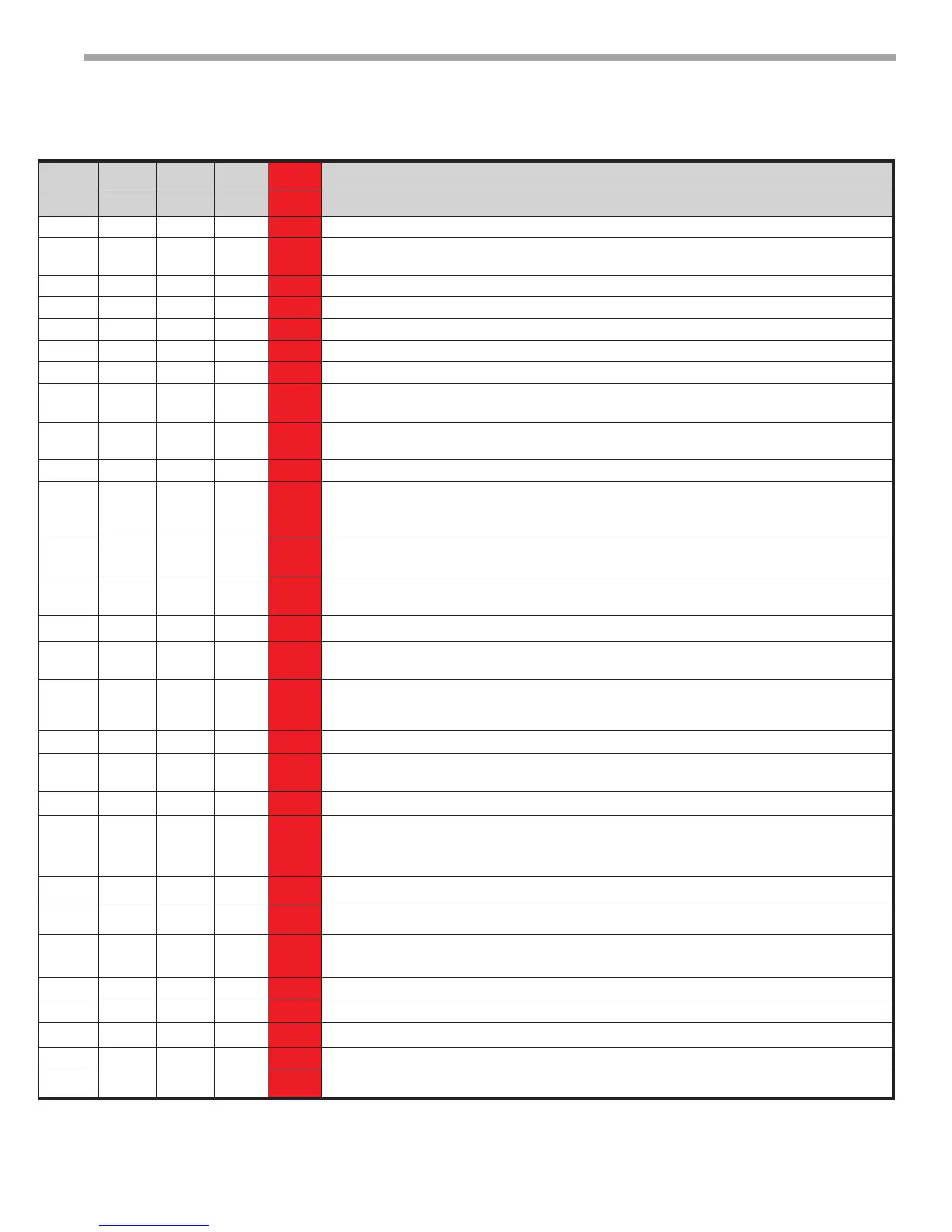
Point Name Type Number
Read/Write
Type Register Type ID NV Name Default Gen 3 Gen 4 Gen 5 Gen 6 Gen 7 Description
BACNet ModBus N2 LON
Dirty Filter Interval AV 30 R/W Float 40027 Data Float 19 nviDFI 1500 Hrs X X X X Time Interval for the time based Dirty Filter Replacement Alarm.
AUX CFG AV 31 R/W Float 29 Data Float 20 nviAuxCfg 1 X X X X
Sets Conguration parameters for the AUX output Relay (W). See AUX CFG SETTINGS
section below.
TSTAT Mode AV 32 R/W 1 X X Determines method of Temp Control in GEN 3 Hardware.
SF CFG AV 33 R/W Float 33 Data Float 22 nviSfCfg 1 X X X X X Sets Conguration parameters for the Supply Fan.
Zone Temp Status AV 34 R Float 30028 Data Float 23 nvoZTStatus NA X X X X Network Output for Space (Room Temp)Temerature. Celsius /Fahrenheit.
LVG Temp Status AV 35 R Float 30030 Data Float 24 nvoLAT NA X X X X Leaving Air Temperature for WSHP. Celsius/ Fahrenheit.
LVG Air Water Temp Status AV 36 R Float 30032 Data Float 25 nvoLWT NA X X X X Leaving Water Temperature for WSHP. Celsius/ Fahrenheit.
Manual SP Adjust AV 37 R/W Float 40035 Data Float 26 nviManSPAdj 5° F X X X X
Network Input for User Dened Fahrenheit Setpoint Adjustment. Should not be used with LSTAT
Sensors If = 0 cannot adjust SP at ASW.
Master ZT Celsius AV 38 R/W Float 40037 Data Float 27 Special* 22.7° C X X X X
Celsius Network input for Multiple WSHP sharing the same Space Sensor This is only for Slave
units where the M/S Switvh is (BV:16) ON.
Unoccupied CL SP Celsius AV 39 R/W Float 40039 Data Float 28 Special* 27.7° C X X X X Network Input for the Celsius cooling setpoint in the unoccupied mode.
Occupied DeadBand Celcius AV 40 R/W Float 40041 Data Float 29 Special* 1.1° C X X X X
Creates the Celsius Heating Setpoint using Occupied Cooling Setpoint minus current value when
using the Dead Band mode. Minimum Value is 1.11° C with a default of 1.11°C. DB Mode
(BV:48) must be "ON".
Slave CL Setpoint Celsius AV 41 R/W Float 40043 Data Float 30 Special* 23.3° C X X X X
Network input for the actual Celsius cooling Setpoint when used as a slave unit. This input is only
used for slave units where the M/S Switch (BV:16) is "ON".
Slave HT Setpoint Celsius AV 42 R/W Float 40045 Data Float 31 Special* 22.2° C X X X X
Network input for the actual Celsius Heating Setpoint when used as a slave unit. This input is only
used for slave units where the M/S Switch (BV:16) is "ON".
Occupied CL SP Celsius AV 43 R/W Float 40047 Data Float 32 Special* 23.3° C X X X X Network Input for the Celsius cooling setpoint in the occupied mode.
Manual Setpoint Adj Celsius AV 44 R/W Float 40049 Data Float 33 Special* 2.7° C X X X X
Network Input for user dened Celsius Setpoint Adjustment. Should not be used with
RS Pro Sensors.
Unoccupied Dead Band AV 45 R/W Float 40015 Data Float 10 Special* 17.0° f X X X X
Creates the Fahrenheit heating setpoint using Unoccupied Cooling Setpoit minus current value
when using deadband mode. Minimum value is 2° F with a default of 17° F. DB Mode (BV:48)
value must be "ON").
RV Status BV 13 R DI 10006 BI 6 nvoRVStatus NA X X X X X Indicates the Reversing Valve Status (ON/ OFF).
Work Schedule BV 14 R/W NA NA NA NA NA NA X X X X X
Reads Schedule from BMS and informs controls whether they are in Occupied or
Unoccupied Mode.
UPS Signal BV 15 R DI 10007 BI 7 Special* NA X X X X X Indicates if the UPS Mode is ON/OFF. Refer to CXM DXM DXM2 AOM for UPS Denition.
M/S Switch BV 16 R/W DO 8 BI 8 nviMS OFF X X X X X
Master/Slave network input to enable the use of Master ZT. Master unit is dened as one WSHP
per sensor and the defaul value is "OFF". Slave is dened as a unit that does not have it's own wall
sensor and that shares a wall sensor with Master unit and the value is "ON".
C1 Rumtime Alarm BV 17 R DI 10008 BI 8 Special* NA X X X X X Indicates the number of operational hours for C1 has exceeded 5000. Reset via C1 Reset(BV:2).
C2 Runtime Alarm BV 18 R DI 10009 BI 9 Special* NA X X X X X Indicates the number of operational hours for C2 has exceeded 5000. Reset via C2 Reset(BV:5).
Dirty Filter Alarm BV 19 R DI 10010 BI 10 nvoDFAlarm NA X X X X X
Indicates the number of Supply Fan operational Hours has exceeded the Dirty Filter Interval setting.
Reset via Dirty Filter Reset (BV:7)
Valid SensorAlarm BV 20 R DI 10011 BI 11 nvoVSAlarm NA X X X X X Indicates there is no valid Room Sensor connected to the MPC Unit.
C1 Cycle Reset BV 21 R/W DO 9 BO 9 Special* OFF X X X X X Network Input to reset the C1 Cycle Counter (AV:20) back to Zero.
C2 Cycle Reset BV 22 R/W DO 10 BO 10 Special* OFF X X X X X Network Input to reset the C2 Cycle Counter (AV:20) back to Zero.
Lockout Alarm BV 23 R DI 10012 BI 12 nvoLOAlarm NA X X X X X Indicates the CXM/DXM/DXM2 is in Lockout Mode.
Fault Coutner Reset BV 24 R/W DO 11 BO 11 Special* OFF X X X X X Network Input used to reset the historical counters for each error code back to Zero.