THE SMART SOLUTION FOR ENERGY EFFICIENCY
MPC MultiProtoCol DDC Controls
November 19, 2018
28
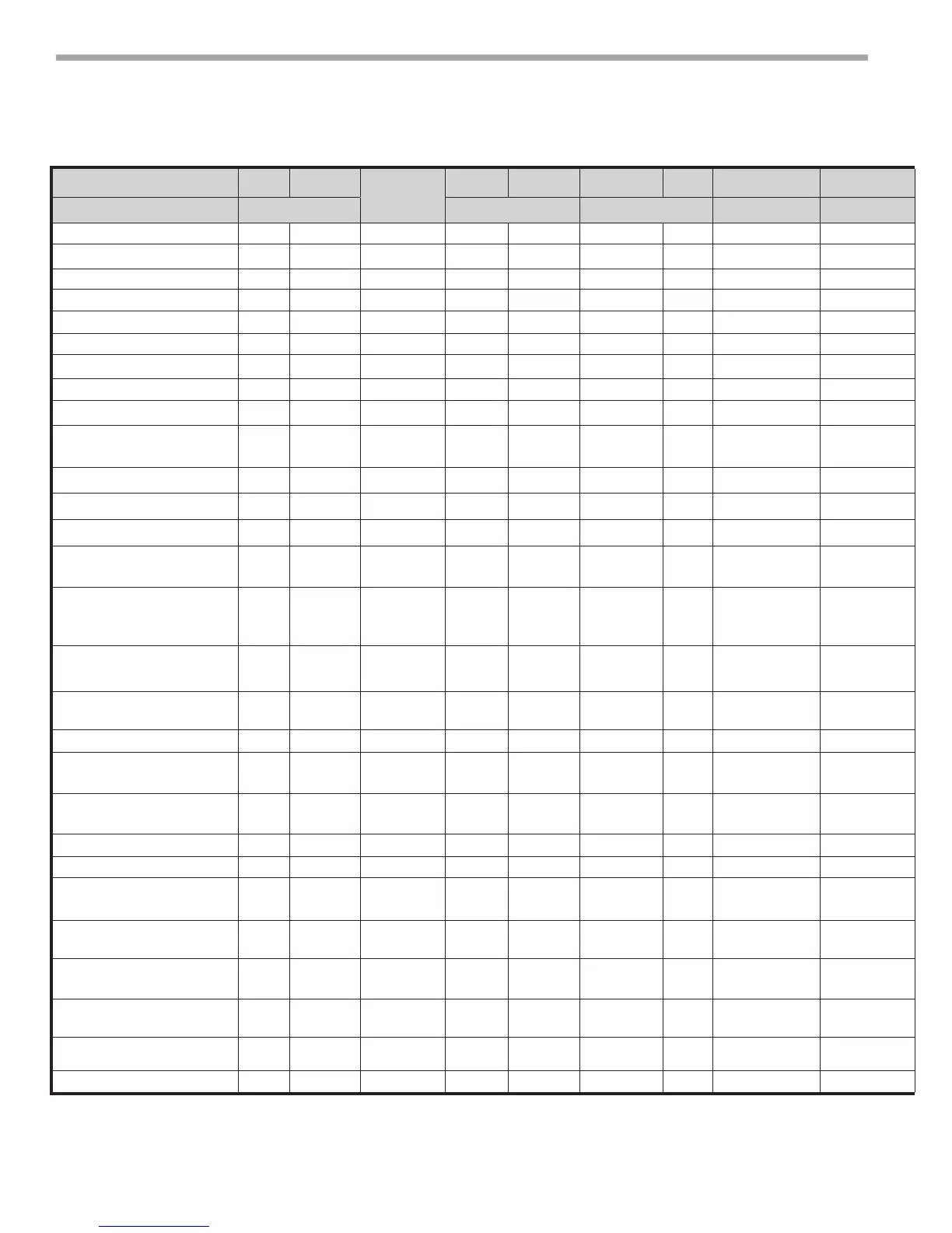
Multi Generation Water-to-Air Points Matrix - cont'd
(Read Left to Right Across Spread)
Point Name Type Number
Read/Write
Type Register Type ID NV Name Default Gen 3 Gen 4 Gen 5 Gen 6 Gen 7 Description
BACNet ModBus N2 LON
C1 Cycle Alarm BV 25 R DI 10013 BI 13 Special* NA X X X X X Indicated the Compressor C1 has cycled ON/OFF more than 5 time during 1 hour.
C2 Cycle Alarm BV 26 R DI 10014 BI 14 Special* NA X X X X X Indicated the Compressor C2 has cycled ON/OFF more than 5 time during 1 hour.
AUX Status BV 27 R DI 10015 BI 15 nvpAuxStatus NA X X X X X Indicates the AUX output (W) is OFF/ON.
SF Manual BV 28 R/W DO 12 BO 12 nviSFMan OFF X X X X X Manual Switch to turn Supply FAN (OFF/ ON). Only Works while in Test Mode.
RV Manual BV 29 R/W DO 13 BO 13 nviRVMan OFF X X X X X Manual Switch to turn Reversing Valve (OFF/ ON). Only Works while in Test Mode.
C1 Manual BV 30 R/W DO 14 BO 14 nviC1Man OFF X X X X X Manual Switch to turn Compressor C1 off or ON. Only Works while in Test Mode.
C2 Manual BV 31 R/W DO 15 BO 15 nviC2Man OFF X X X X X Manual Switch to turn Compressor C2 off or ON. Only Works while in Test Mode.
TSTAT Reset BV 33 R/W ADF 28 Coil 29 nviTstatMode OFF X Obsolete Point found only in Gen 5.
AUX Manual BV 32 R/W DO 16 BO 16 nviAuxMan OFF X X X X X Manual switch to turn AUX Ouput (W) "OFF" or "ON". Only works while in Test Mode.
Test Mode BV 34 R/W DO 18 BO 18 nviTestMode OFF X X X X
Network input used to bypass normal operations in order to operate the unit manually,
maximum ON time for Test Mode is 60 Minutes.
Test Mode BV 37 R/W X Manual switch to turn AUX Ouput (W) either "OFF" or "ON".
Test Mode Alarm BV 38 R DI 10025 BI 21 Special* NA X X X X Indicates the unit is still in Test Mode after the test mode timer has expired.
Metric BV 33 R/W DO 21 BO 28 Special* OFF X X X X Network input used to dene inputs and outputs. Celsius- ON / Fahrenheit -Off.
AUX Toggle BV 40 R/W DO 17 BO 17 nviAuxToggle OFF X X X X
Network input used to toggle the auxillary output (W) "ON" and "OFF" Used when AUX
CFG (AV:31) is set to a value of 11.
Unoccupied Deadband
Celsius
AV 46 R/W Float 40017 Data Float 11 Special* 9.44° C X X X X
Creates the Celsius Heating Setpoint using Unoccupied Cooling Setpoint minus current value
when using the Deadband Mode. Minimum value is 1.1° C with default of 9.44° C . DB Mode
(BV:48) must be "ON".
Relative Humidity Setpoint AV 47 R/W Float 59 Data Float 38 nviRHSP 60% X X X
Network input for the Dehumidication Setpoint above which the Auxillary output(W) is activated
when AUX CFG (AV:31) is set to 12 for Humidity Control.
Relative Humidity Deadband AV 48 R/W Float 61 Data Float 39 nviRHDB 5% X X X
Creates Dehumidifcation turn off point using Relative Humidity SP minus the RH current value
when AUX CFG ( AV:31) is set to 12 for Humidity Control.
Relative Humidity Status AV 49 R Float 34 Data Float 40 nvoRHStatus NA X X X Network Output for Space Relative Humidity when using appropriate sensor.
Aux 5 Temp AV 50 R Float 36 Data Float 41 nvoAux5Temp NA X X X
Network Output for Auxillary Temperature 5 when RNET Mode (BV:44) is "ON" and AUX 5 CFG
(BV:47) is set to "ON" for temperature sensor.
Aux 6 Temp AV 51 R Float 38 Data Float 42 nvoAux6Temp NA X X X
Network Output for Auxillary Temperature 6 when RNET Mode (BV:44) is "ON" and AUX 6 CFG
(BV:46) is set to "ON" for temperature sensor.
CO2 Status AV 52 R Float 40 Data Float 43 nvoCO2Status NA X X X Network Output for Space CO2 level when using the appropriate sensor.
VOC Status AV 53 R Float 42 Data Float 44 Special* NA X X X Network Output for Space VOC level when using the appropriate sensor.
CO2 Trip point AV 54 R/W Float 63 Data Float 45 nviCO2Trip 800 PPM X X X
Network Input for CO2 trip point above which the Auxillary Output is activated when AUX CFG
(AV:31) is set to13 for CO2 Control.
VCO Trippoint AV 55 R/W Float 65 Data Float 46 Special* 800 PPM X X X
Network Input for VOC trip point above which the Auxillary Output is activated when AUX CFG
(AV:31) is set to 14 for VOC Control.
FAN Speed Trigger AV 56 R/W Integer 67 Data Int 12 nviFanSpdTrig 75% X X
Network input for Heating or Cooling PID above which the AUX Output (W) turns "ON" when AUX
CFG is set to 5 for Fan Speed Control. Requires eld wired relay for PSC Motors Only.
Airow Fault Counter AV 57 R Integer 44 Data Int 13 Special* 0 X X
Indicates the number of airow faults that have occured since unit startup or resetting the fault
counter via Fault Count Reset (BV:24).
Pump Fault Counter AV 58 R Integer 45 Data Int 14 Special* 0 X X
Indicates the number of pump faults that have occured since unit startup or resetting the fault
counter via Fault Count Reset (BV:24).
Application Type AV 99 R Float 13 Data Float 9 NA NA X X X Factory Use Only.