IGS-NT Installation Guide
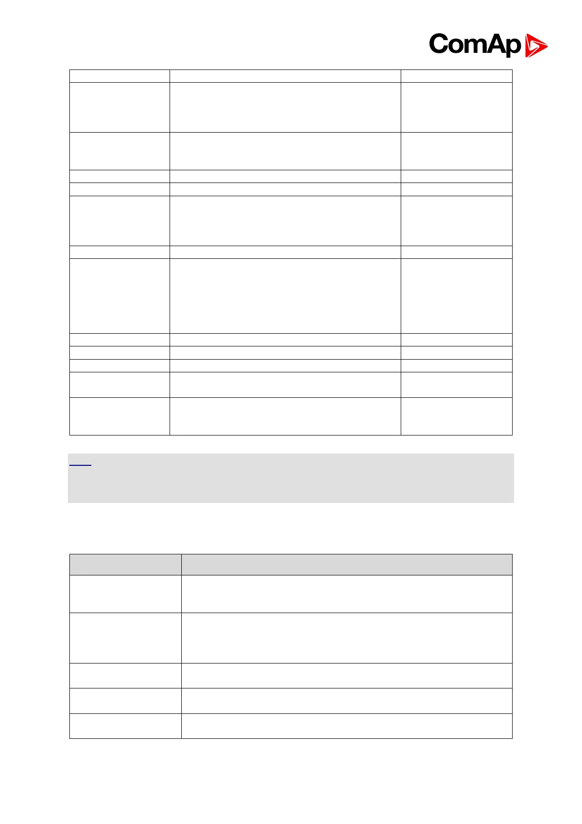
IG-AVRi-
TRANS/LV
IG-AVRi-
TRANS/100
Voltage transformer for supplying AVRi module
RS232 (InteliMonitor, GenConfig)
communication cable
(It is not a part of controller delivery.)
External analog inputs unit
Replaces IG-MU and I-LB (RS232/RS485
communication speed increased to 57600
bps); communication with multiple controllers
to a local PC.
I-CB/CAT-Gas
I-CB/CAT-Diesel
I-CB/MTU
I-CB/MTU-
SIAM4000
I-CB/DeutzTEMe
Inteli - Communication Bridge:
Interface unit for some types of engines with
ECU (without J1939)
External analog, binary I/O unit
Voltage transformer unit to separate mains and
generator voltage measurement
Voltage transformer unit with voltage ratio 2:1
to separate mains and generator voltage
measurement
HINT
Controller central unit contains complete hardware for all applications. Number of inputs and
outputs can be expanded by additional modules IS-AIN8, IS-BIN16/8, IGS-PTM, IGL-RA15, I-
AOUT8.
3.2.3. Dongle overview
No dongle for Single Parallel to Mains (SPtM) is required. No
dongle for Single Prime Mover (MINT in SPM application) is
required.
Dongle for multiple applications MINT with Load sharing, Var
sharing and Power management function. This dongle should be
used for SUS and GeCon MINT applications from versions SUS-1.3
and GeCon-3.0 (Marine and Landbased)
Obsolute. Dongle for multiple application SUS MINT with Load
sharing, Var sharing and Power management function
Obsolute. Dongle for SUS in Single Parallel to Mains application.
Not needed from version SUS-1.3
Obsolute. Dongle for multiple application GeCon MINT with Load
sharing, Var sharing and Power management function