IGS-NT Installation Guide
7.4.2. Terminals, Inputs and Outputs
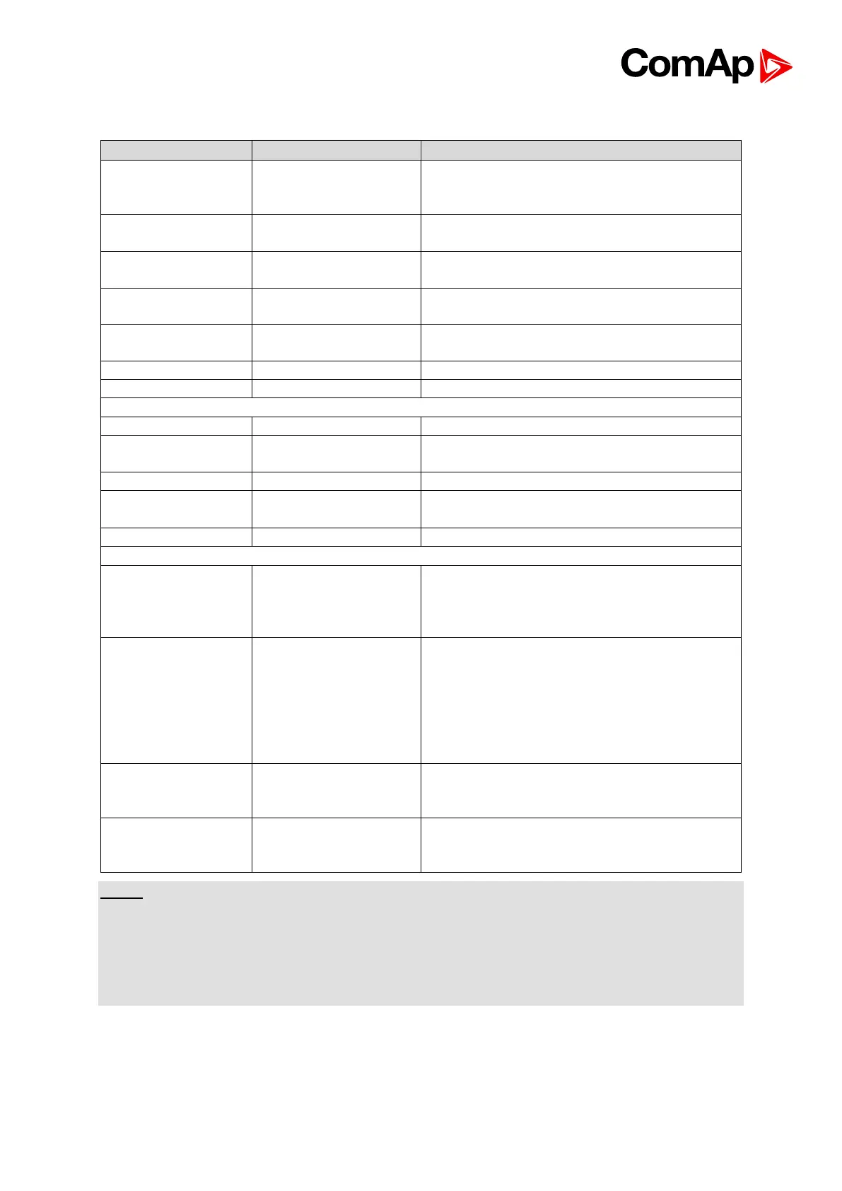
277 Ph-N or 480 Ph-Ph VAC
(neutral not needed), max 600VAC *, CAT
III
277 Ph-N or 480 Ph-Ph VAC
(neutral not needed), max 600VAC, CAT III
L1k,L1l, L2k,L2l,
L3k,L3l
0 ÷ 5 Amps, max 10 A all time, 150 A for 2
sec
0 ÷ 5 Amps, max 10 A all time, 150 A for 2
sec
TTL (5V PWM) interface to IG-AVRi
Activation to minus power supply.
Load is connected to plus or minus power
supply (defined in GenConfig).
Speed governor output interface (10V / 5V
PWM; 500 – 3000Hz)
Min 2 Vpk-pk (from 4 Hz to 4 kHz)
PC: InteliMonitor, GenConfig or
Modem, GSM modem or
ECU (e.g. Cummins ModBus) or InteliVision
8
RS485 (Display) **
non isolated
IG-Display (Remote display) or InteliVision 8
(remote display) or for PC (via RS485
converter) = redirected RS232 (1)
see Basic settings: RS485(1)conv.
For IG-Display and InteliVision 8, the
setpoint RS485 (1) conv has to be set to
DISABLED value.
Extension modules: IS-AIN8, IS-
BIN16/8,IGS-PTM, IGL-RA15, I-AOUT8,
ECU
Intercontroller (Load&VAR sharing, Power
management) and monitoring (IG-IB, I-LB)
and up to 4 InteliVision 8 displays
NOTE:
* IG-MTU or IG-MTU-2-1 can be used for three wire systems, systems with separated
Neutral or when galvanic separation between generator or mains voltage and controller is
required.
** When more devices connected to RS485 bias resistor jumpers should be closed only on
one of them.