17. Speed governor and AVR
general settings
17.1. Sync/load control adjustment
Hint:
Use isochronous speed governor.
Two wire shielded connection from IGS-NT SPEED GOVERNOR output (SG OUT, SG
COM) to Speed governor auxiliary input is recommended.
A full range change of the IGS-NT speed governor output (from SpeedGovLowLim to
SpeedGovHiLim) should cause 5-10% change of the engine speed (SpeedGovLowLim ~
95% RPM
nom
, Speed gov bias ~ 100% RPM
nom
, SpeedGovHiLim ~ 105% RPM
nom.
IMPORTANT
Speed governor has to be adjusted for optimum performance before Sync / load
control adjusting.
Check generator phase sequence before the first GCB connection.
Before optimal sync/load control settings are adjusted, please disconnect GCB
OPEN/CLOSE output or set Phase window = 0 to avoid paralleling when adjusting
settings.
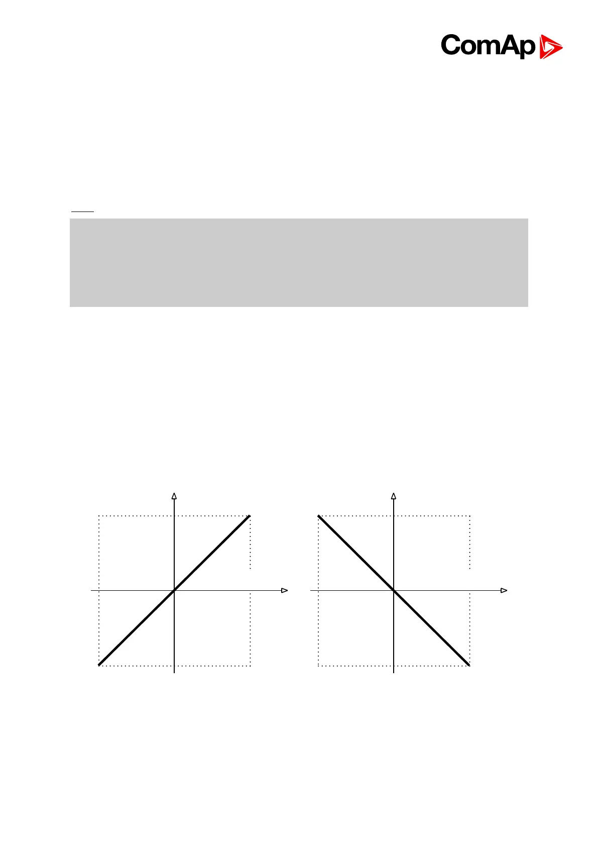
17.1.1. Speed governor output characteristics
SpeedRegChar = POSITIVE SpeedRegChar = NEGATIVE
17.1.2. Synchronizer adjustment
1) Start the engine in MAN Mode.

 Loading...


