IGS-NT Installation Guide
Resistance input 0-2400 Ω
For more info see the chapter
Speed Governor Output
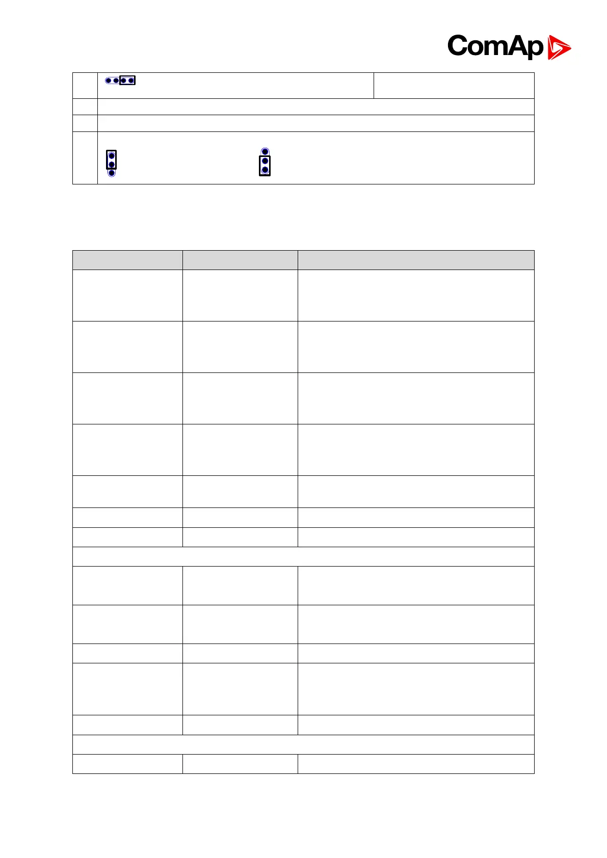
Boot jumper (upper one, rest of the jumpers is for internal use only)
Left to right: Pull up Bias / 120Ω / Pull down Bias
AOUT setting
Voltage 0-10VDC Current 0-20mA
7.6.2. Terminals, Inputs and Outputs
3x120 / 277 Ph-N or 207 / 480 Ph-Ph VAC
(neutral not needed), max 350 / 600VAC *,
CAT III
3x120 / 277 Ph-N or 207 / 480 Ph-Ph VAC
(neutral not needed), max 350 / 600VAC,
CAT III
L1k,L1l, L2k,L2l,
L3k,L3l
0 ÷ 5 Amps, max 10 A all time, 150 A for 2
sec
0 ÷ 1 Amp, max 2 Amps all time
0 ÷ 5 Amps, max 10 A all time, 150 A for 2
sec
0 ÷ 1 Amp, max 2 Amps all time
TTL (5V PWM) interface to IG-AVRi
Activation to minus power supply.
Load is connected to plus or to minus power
supply. (defined in GenConfig).
SG-OUT, SG-COM
AOUT+, AOUT-
COM
Speed governor output interface (10V / 5V
PWM; 500 – 3000Hz)
Configurable analog output, mA, V.
Min 2 Vpk-pk (from 4 Hz to 4 kHz)
PC: InteliMonitor, GenConfig or