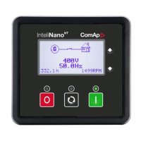
InteliNano-NT Plus, SW version 2.0.1.x, ©ComAp – July 2015
12
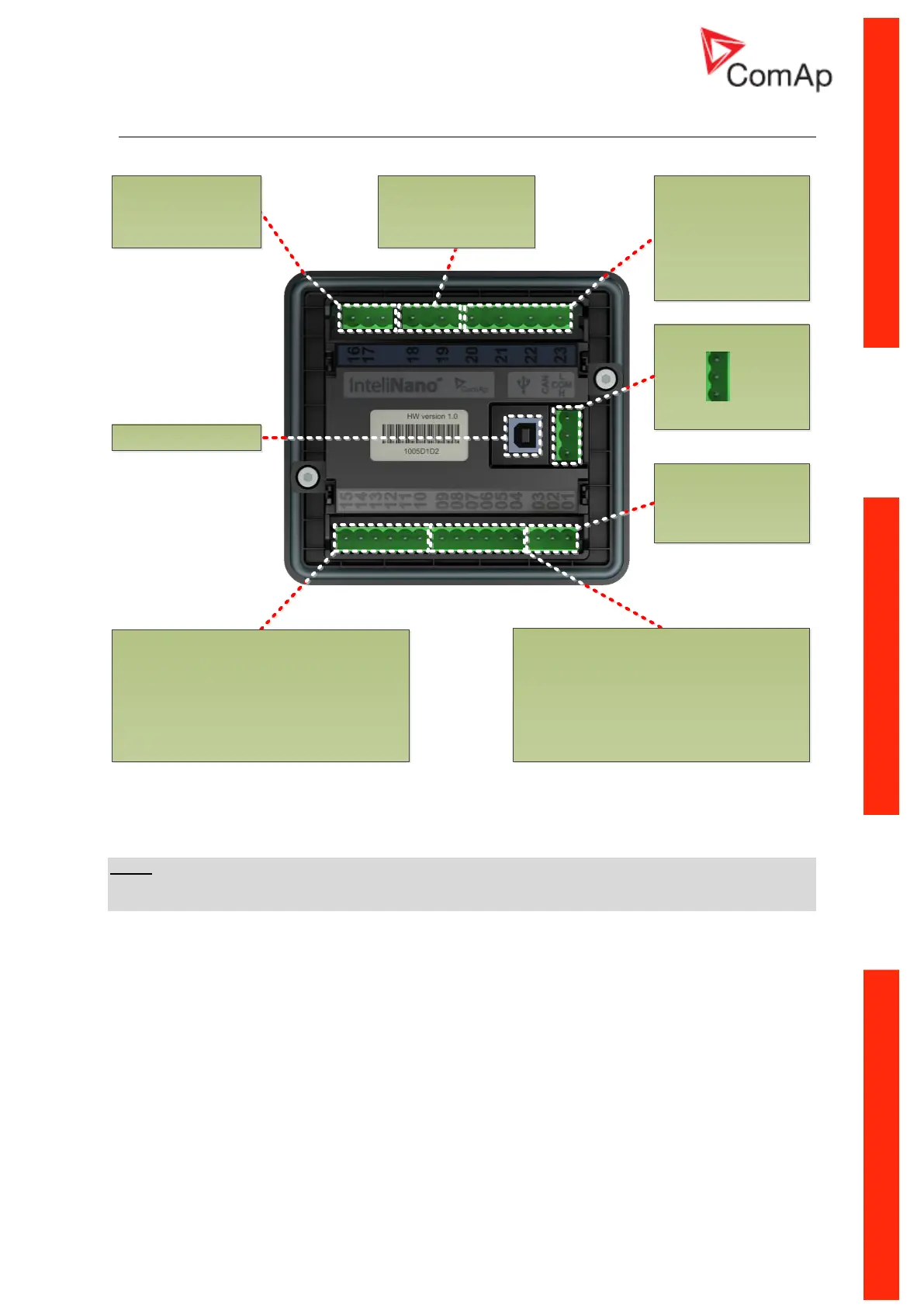
Terminal diagram 4.3
CAN INTERFACE
MAINS / GENERATOR
VOLTAGE
MEASUREMENT
T20 = Neutral
T21 = Phase 1
T22 = Phase 2
T23 = Phase 3
GENERATOR CURRENT
MEASUREMENT
T16 = k
T17 = l
USB interface
L
COM
H
INTPUT TERMINALS
T10 = COM for analog inputs
T11 = binary input
T12 = binary input
T13 = binary/analog input – Low Fuel Level
T14 = binary/analog input – Coolan Temperature
T15 = binary/analog input – Oil Pressure
OUTPUT TERMINALS
T04 = binary output – Starter (6A)
T05 = binary output - Fuel Solenoid (6A)
T06 = binary output (500 mA)
T07 = binary input/output (500 mA)
T08 = binary output (500 mA)
T09 = binary output (500 mA)
POWER SUPPLY, D+
T01 = BATT -
T02 = D+
T03 = BATT +
GENERATOR VOLTAGE
MEASUREMENT
T18 = Neutral
T19 = Phase 1
Figure 4.2
INTELINANO
NT
PLUS TERMINALS DESCRIPTION
NOTE:
In case the InteliNano Plus controller is used as MRS controller the terminals T20, T21, T22 and T23
are used for generator voltage measurement.

 Loading...