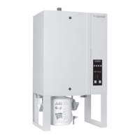
Control voltage supply Uc
Caution!Beforeconnecting,makesurethatthemainsvoltagecorrespondswiththecontrol
voltage of the unit (200…240 V, 50…60 Hz).
Caution!Thehumidiermustonlybeconnectedtoamains supply with a protective con-
ductor.
TheconnectiontothecontrolvoltageUcismadeinaccordancewiththeconnectionschematic,tothe
terminal “X1” on the supply module. The customer is to install a service switch Q4 in the supply line
(allpoledisconnectingdevicewithaminimumcontactopeningof3mm)andanF4 fuse (max. 10 A
slow acting) (thesearebothessentialrequirements).
Note:Onversionsinwhichtwounitsareincorporated,thecontrolvoltageconnectionismadetothe
unitttedwiththedisplayandoperatingfacility(unitA).Theterminal“X1”ofthesecondunit(unitB)
remains unused. To supply the control voltage to unit B, the terminals “X6” on the supply modules of
both units must be connected using the supplied cable.
Thecross-sectionofthemainscablemustcomplywiththeapplicablelocalregulations(minimumof
1.5 mm
2
).
External safety circuit
Toensurethesafetyofthehumidiersystem,itisessentialthataso-calledexternalsafetycircuitbe
provided to monitor the operation.
To this end, the potential-free contacts (max. contact loading 250V/5A) oftheexternalmonitoring
devices(e.g.maximumhumidistat,owmonitor,ventilationinterlock,etc.)areconnectedin series with
the corresponding contacts on the terminal “X1”,inaccordancewiththeconnectionschematic.
Caution, danger of electric shock! The mains voltage is connected to terminal “X1” (up to
240V).Thesteamhumidiermustthereforebeisolatedfromthemainssupply(powerandcontrol
components),beforestartingtheconnectionwork.
If,forwhateverreason,noexternalmonitoringdevicesareconnected,aconnectingbridge“J”mustbe
installed on the appropriate contacts on the terminal strip “X1”.
Do not apply any extraneous voltage to the terminals.
Thecross-sectionofthecablemustcomplywiththeapplicablelocalregulations(minimumof1mm
2
).
Remote operating and fault indication H1 (Option “RFS”)
TheoptionalremoteoperatingandfaultindicationPCBistobeconnectedviatheconnectionsocket
“J3”onthecontrolboard.TheremoteoperatingandfaultindicationPCBcontainsthepotential-free
relaycontactsK1…K4fortheconnectionofthefollowingoperatingandfaultindications:
– K1 “Steam production”: This relay closes as soon as the unit produces steam.
– K2 “Fault”: This relay is activated if there is a fault.
– K3“Maintenance”: Thisrelayisactivatedwhenthesetserviceintervalhasexpired.
– K4“UnitOn”: Thisrelayclosesassoonastheunitisswitchedonviathemainswitch.
The maximum contact loading is 250V/5A.
Appropriatesuppressormodulesaretobeusedfortheswitchingofrelaysandminiaturecontactors.